background image


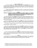
IMPORTANT!

  READ AND FOLLOW 

ALL

 INSTALLATION AND MAINTENANCE INSTRUCTIONS, INCLUDING 

CLEANING THE UNIT AS SPECIFIED, AND REPLACING GASKETS ANNUALLY, AND PARTS AS NEEDED. 

ENGLANDER IS NOT RESPONSIBLE FOR ANY DAMAGE OR INJURY INCURRED DUE TO NEGLECT, OR DUE TO 

UNSAFE INSTALLATION OR USAGE OF THIS PRODUCT. CALL TECHNICAL SUPPORT WITH ANY QUESTIONS. 

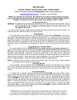
lantern fuel, kerosene, charcoal lighter fluid, diesel fuel or any other flammable liquid to start the 

fire.   Do not use the manual startup method if the igniter is working.  NEVER place firestarter 

near the igniter.  

If you have continued problems with the Auto-Start Igniter, call Technical Support. 


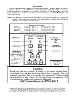
E-Codes 


“E-Codes,” or Error Codes, are codes  that  will appear in the Heat  Range and Blower Speed 

windows of the Control Board if your unit experiences problems.  If you receive any of these codes, 

first attempt to reset your unit by pressing the “ON” button (only once).  If the unit continues  to 

display any E-Code(s), please contact Technical Support at (877) 356-6663 before further attempting 

to restart your unit. 


1. E-1 = Vacuum Loss 

        2. E-2 = Fail to Start 

        3. E-3 = Over Temperature Limit 


NOTE:  “E-0” indicates “No Error” 


First Fire: Adjust the “Heat Range” to a “5” setting


and allow the stove to burn in this manner 

for 

at least

 three (3) hours. This will allow the unit to “cure out” as the paint and the 

oils from the manufacturing process  burn off. Remember to open a door and/or 

window to ventilate the area. You may find it necessary to open several doors or 

windows for plenty of ventilation. 


Subsequent Cold Starts: In a cold start situation, the unit should be operated at a “5” setting 

until the room air blower begins to operate.  


NOTE:

  The start-up cycle for this unit with the Auto-Start Igniter is 13 minutes.  Press the 

“ON” button only once on start-up.  Pressing the “ON” button a second time during 

the start-up cycle will cause the start-up cycle to begin again. 


IMPORTANT:


If the  unit fails to start properly, or does not properly complete the Shut-Down 

procedure, 

open the closest outside door and a window to eliminate the home’s 

natural draft BEFORE opening the stove’s door or hopper lid.

  This will allow 

any smoke to exit through the external air hook-up instead of spilling into the home. 


SHUT-DOWN PROCEDURE 


WARNING: NEVER SHUT DOWN THIS UNIT BY UNPLUGGING IT FROM THE POWER SOURCE. 


Refer to the following instructions: 

Press the “OFF” touch pad to put the stove in the “Shut-Down”  mode.  There will be an  

S D


in the Heat Range and Blower Speed windows while the unit is shutting down to verify this.  At 

this time the red light above the “OFF” pad will illuminate. When the “OFF” pad is touched the top 

auger will instantly stop feeding pellets to the bottom auger tube, but the room air blower, exhaust 

blower and bottom auger will continue to operate. When the internal temperature drops to 95 

degrees the room air blower will cease to operate, and when the internal temperature drops to 90 

degrees the bottom auger and exhaust blower will stop. The red light will then shut off and the entire 

stove will be shut down. The hotter the unit is operating, the longer it will take for the stove to 

complete the Shut-Down cycle. 


Note:  

The unit will exit the Shut-Down cycle if you press any buttons during Shut-Down. 


Note: 

If the room temperature stays above 70 degrees the stove will remain in the Shut Down mode 

for 60 minutes, regardless of the temperature reading at the heat sensor. If the stove stays on 

longer than 60 minutes the unit will automatically turn off. 

Summary of Contents for 25-PDVC

Page 1: ...l inc PO Box 206 Monroe VA 24574 United States Pellet Stove MODELS 25 PDVC 25 PDVCH 55 SHP10 55 SHP10L 55 TRP10 SAVE THESE INSTRUCTIONS www englander stoves com Support 877 356 6663 Email tech sbi international com 46313A 2022 11 21 Safety tested by an accredited laboratory ...

Page 2: ...des 14 Shut Down Procedure 14 Daily Operation 15 Refueling 15 Power Outage 15 Fuel Outage 15 Combustion Blower Failure 15 Ash Removal Maintenance Daily 16 Semi Weekly 16 Monthly 17 Annual 17 Rear Panel Removal 18 Auger Motors 18 Auger Bearings Shafts 18 Convection Blower 18 Combustion Blower 18 Vacuum Switch 19 Vacuum Switch Port 19 Hopper Lid Switch 20 Gaskets 20 Finish 20 Glass 20 Control Board ...

Page 3: ...LLATION INSTRUCTIONS CONTACT YOUR LOCAL BUILDING OR FIRE OFFICIALS FOR RESTRICTIONS AND INSTALLATION INSPECTION REQUIREMENTS INCLUDING PERMITS IN YOUR AREA Questions Need Parts or Options www englander stoves com Englander highly recommends the use of smoke detectors and Carbon Monoxide detectors with any hearth product including this unit Follow all manufacturer s instructions when using smoke or...

Page 4: ...ULC S627 EPA Test Method ASTM E2779 CSA B415 1 ASTM E2515 Notes for this unit Product may vary slightly from diagram Clearances are the minimum for this unit and may need to be increased in the rear to have proper vent clearances Follow all venting manufacturer clearances and local codes As tested per ASTM 2779 Heat output burn rate and maximum burn time are heavily dependent on the type of pellet...

Page 5: ...department at 877 356 6663 if you need any help with your unit We are nearly always able to help walk you through any repairs problems or questions you may have PLEASE NOTE While information obtained on our web site and through our number is always free of charge there will be a service charge incurred with any on site repairs or maintenance that we may arrange Wishing you years of efficient quali...

Page 6: ...nace you must place your stove at least 20 feet 20 from the Cold Air Return We recommend you open an outside window slightly and never close the door that leads from this room to the rest of your home IN THE EVENT OF SMOKE BACK 1 If you see smoke coming out of your unit into the room due to a power failure DO NOT OPEN THE HOPPER OR DOOR TO YOUR UNIT Remain calm DO NOT UNPLUG UNIT Open the nearest ...

Page 7: ...e U L approved twist lock pellet pipe be sure to use U L approved Pellet Vent pipe and fasten each joint of the pipe with at least three screws ULC approved if Canada Outside combustion air is mandatory for these units to work properly Make this connection using a 1 7 8 I D metal pipe steel aluminum or copper and coupler Be sure to secure the pipe to the unit with a clamp or aluminum tape The outs...

Page 8: ...NEVER place any firestarter on any hot surface or hot coals Never apply any firestarter products of any kind to a hot surface or hot coals 18 Basement Installation We recommend basement installation be performed only by a professional installer For basement installations a 3 three inch pipe and coupler must be used for Outside Combustion Air and a minimum clearance of 3 three feet must be maintain...

Page 9: ...EM SERVING ANOTHER HEATING APPLIANCE Through the Wall To vent the unit through the wall connect the pipe adapter to the exhaust motor adapter If the exhaust adapter is at least eighteen inches 18 above ground level a straight section of pellet pipe can be used to initially pass through the wall see Illustration 1 Your dealer or our factory should be able to provide you with a kit that will handle ...

Page 10: ... professional can confirm this upon inspection Outside Air Outside Combustion Air Intake Outside air is mandatory for this unit to operate properly This unit has been designed and tested with this connection because so many homes are airtight and there is not adequate combustion air available inside the dwelling The air intake pipe is located on the bottom side of the burn pot from the rear and me...

Page 11: ...three inches 3 or 76 2mm is required to the rear wall However be sure to follow the vent manufacturer s clearances as well See the stove s safety tag and call 877 356 6663 with any questions 1 If 3 flue pipe exceeds 15 in length increase to 4 flue pipe for remaining flue connections 2 Total flue length should not exceed 35 3 Horizontal run not to exceed 4 4 Floor protector must extend 6 from front...

Page 12: ...THE ROOF SURFACE Notes on termination of Pellet Vent Pipe from NFPA 211 2006 ed Section 10 4 Termination 10 4 5 See also FLUE SYSTEM section of manual AND additional notes above Not less than three 3 feet above any forced air inlet located within ten 10 feet Not less than four 4 feet below four 4 feet horizontally from or one 1 foot above any door window or gravity air inlet into any building Not ...

Page 13: ...he ON button to begin the dry run After the 20 minute dry run the control board will return to OFF An error code will appear in the Heat Range and the Blower Speed windows as E 2 which means the unit failed to start normally After this code is received and you are sure the unit is working properly fill the hopper with wood pellets IMPORTANT VERIFY all parts are properly operating BEFORE pouring in...

Page 14: ...to operate NOTE The start up cycle for this unit with the Auto Start Igniter is 13 minutes Press the ON button only once on start up Pressing the ON button a second time during the start up cycle will cause the start up cycle to begin again IMPORTANT If the unit fails to start properly or does not properly complete the Shut Down procedure open the closest outside door and a window to eliminate the...

Page 15: ...the hopper lid or the door to the unit during power outage Open the closest outside door and a window to eliminate the home s natural draft Wait for power to be restored and then press the ON button to re start the unit if necessary We highly recommend the use of a surge protector with your unit as power surges and failures can affect the operation of any electrical appliance We do not recommend l...

Page 16: ... Remove and clean the burn pot wear plate refer to the exploded diagram in the rear of this manual Illustration 6 and the close up diagram shown here and remove any ash build up in the area below the wear plate Also be sure there are no ashes or obstructions in the tube under the wear plate Check for any build up in the front of the burn area Clean out all air holes if necessary a 1 8 drill bit ca...

Page 17: ...n residue from the feed tube is essential for proper operation of the feed auger which is designed to float freely in the feed tube allowing smooth fuel flow a lesser possibility of a jam and a quieter unit Annual Cleaning The stove and the flue system should be given a complete cleaning at the end of the heating season Remove the burn pot assembly clean it thoroughly and re install it refer to Il...

Page 18: ...ger Bearings and Auger Shafts The auger bearings Part PU UCF204 12 are a sealed unit and do not require lubrication To replace the Top Auger all the fuel must be removed from the hopper as well as from the Top Auger assembly Once this is done the four bolts that hold in the bearing can be removed followed by the complete auger assembly Loosen the two 2 set screws with a 1 8 Allen wrench which will...

Page 19: ...or shut the unit off if the unit turns off an E 1 Code error code will appear in the Heat Range and Blower Speed windows of the Control Board Situations which could cause this include power failure Combustion Blower failure improper flue installation a blocked flue from rodents nests etc or dirty burning from burning improper fuel see Important Information at the beginning of the manual Door Ajar ...

Page 20: ... new adhesive you may have to scrape the old cement from the door channel Once the cement and gasket have been added the door should be closed and latched for twenty four hours to allow the cement to harden If you are replacing the window gasket Part AC GGK the new gasket will already have adhesive on one side Remove the paper on the adhesive side and place the gasket around the outside edge of th...

Page 21: ...ld not require any changes See Operating Instructions and Daily Operation section of the manual for instructions on other Control Board settings Recommended Heat Ranges Low Burn Heat Range setting 1 Room Air Blower setting 1 Medium Low Heat Range setting 2 3 Room Air Blower setting Medium High Heat Range setting 5 8 Room Air Blower setting High Burn Heat Range setting 9 Room Air Blower setting 9 N...

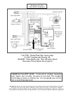
Page 22: ...E OF THIS PRODUCT CALL TECHNICAL SUPPORT WITH ANY QUESTIONS CAUTION Moving Parts May Cause Injury Do NOT Operate with Panel s Off DANGER Parts May Be Hot Risk of Electric Shock Disconnect Power Before Servicing Unit Illustration 4 PU CB19 Control Board Wiring Diagram IMPORTANT SAFETY NOTE If the unit or chimney connector pipe glows red or white the stove is over fired This condition could cause a ...

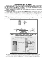
Page 23: ... be needed two inch wrenches or a inch wrench and a inch socket In order to adjust the latch first with the unit unplugged and cooled down open the hopper lid and then lock the latch in its closed position Then take the inch wrench and loosen the nut closest to the latch This nut is then adjusted closer to the lid itself to tighten the latch After adjusting this nut to the desired location hold th...

Page 24: ... cold starts Please Note the unit will not turn On and Off when using the thermostat It will go into an Idle Mode when it reaches the set temperature AC 106 PBN Window Trim Window trim can be attached by using the provided spring clip s and some high temperature silicone optional Insert the tee end of the spring clip into the channel on the edge of the trim then turn the clip and set the other end...

Page 25: ... for earlier models order PU 103 50 25 on diagram PU UCF204 12 Auger Bearing 16 on diagram PU 2X570 Locking Collar 17 on diagram PU CB19 Digital Control Board 12 on diagram PU CB04 if stove Serial Number is below 150 000 CU VS Vacuum Switch See wiring diagram pg 19 PU CBMG Combustion Blower and Motor Gasket 10 on diagram PU BPG Burn Pot Gasket 6 on diagram PU ABGN Auger Bearing Gasket 15 on diagra...

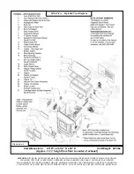
Page 26: ... PARTS AS NEEDED ENGLANDER IS NOT RESPONSIBLE FOR ANY DAMAGE OR INJURY INCURRED DUE TO NEGLECT OR DUE TO UNSAFE INSTALLATION OR USAGE OF THIS PRODUCT CALL TECHNICAL SUPPORT WITH ANY QUESTIONS Pellet Stove Exploded View Diagram Illustration 6 Unit Dimensions 24 W x 28 1 2 H x 28 D Unit Weight 285 lbs Approx 13 height from floor to center of exhaust ...

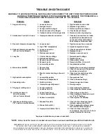
Page 27: ...r 3 Replace vacuum sensor 5 Lazy fire 1 Control board settings 1 Review board settings 2 Bad exhaust blower 2 Replace blower 3 Excessive pellet moisture 3 Keep pellets inside 4 Excessive ash 4 Remove baffles Clean unit 5 Low quality pellets 5 Use premium pellets 6 Blown fuse 6 AMP 1 Power surge 1 Replace fuse use surge protector 2 Exposed wire 2 Check for exposed or frayed wire and loose connectio...

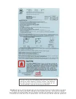
Page 28: ... DAMAGE OR INJURY INCURRED DUE TO NEGLECT OR DUE TO UNSAFE INSTALLATION OR USAGE OF THIS PRODUCT CALL TECHNICAL SUPPORT WITH ANY QUESTIONS You may write your unit s Manufacture Date and Serial Number in the blank spaces on this sample tag for future reference This sample tag also shows the safety info such as UL ULC testing standard etc for your local officials or anyone else who may need referenc...

Page 29: ...ns and Exclusions Damage from over firing will void your warranty This warranty does not apply if damage occurs because of an accident improper handling improper installation improper operation abuse or unauthorized repair made or attempted to be made The manufacturer is not liable for indirect incidental or consequential damages in connection with the product including any cost or expense or serv...

Page 30: ...n within thirty 30 days from the original date of purchase Use any of these three easy ways to send your warranty information in Mailing Address Stove Builder International inc 250 rue de Copenhague St Augustin de Desmaures Québec Canada G3A 2H3 Fax Number 418 878 3001 Twenty four hours a day Online Registration Visit our warranty registration website at http www englander stoves com WARRANTY CARD...

Page 31: ...________ DEALER INFORMATION Purchased From Dealer ___________________________________________ Address _________________________________________________________ City ________________________ State __________ Zip _________________ UNIT INFORMATION Please be sure to refer to sticker on back of manual or box to complete this section Model Number _______________________ Purchase Date __________________...

Page 32: ...bustion air is MANDATORY for proper safe operation and to achieve optimal emissions performance Observe the vent termination clearances specified in your owner s manual and contact our Technical Support if you have any questions Phone 877 356 6663 or email tech sbi international com Be certain that all aspects of the venting system are installed to the venting manufacturer s instructions particula...

Page 33: ...hanical draft system other than direct vent appliances sealed combustion system appliances shall be located in accordance with the following a Not less than 3 ft 91 m above any forced air inlet located within 10 ft 3 0m b Not less than 4 ft 1 2 m below 4 ft 1 2 m horizontally from or 1 ft 305 mm above any door window or gravity air inlet into any building c Not less than 2 ft 0 61 m from an adjace...

Page 34: ...avoided Due to frictional resistance in pipe any excessive outside air piping can result in poor stove performance A screen or other protection device must be fitted over the outside air termination point to prevent rain debris and nuisance animals from entering the piping system Increase the outside air pipe size to 3 0 in diameter pipe if the outside air connection is more than 6 ft in length mo...

Page 35: ...s pellet burning room heater is equipped with a specially designed burn pot which comes preinstalled from the factory This burn pot elevates the burning pellets and delivers air at the precisely required locations Pellets must only be burned in the factory burn pot no modifications should be made to this burn pot and no additional grates or other fire elevators should be used WHAT FUELS NOT TO USE...

Page 36: ...d turn red and the board should display S d shortly after pressing the button This initiates the shut down sequence and the stove will remain in shut down mode until it has cooled down To increase the heat output of the stove press the Up heat range button The number in the heat range display window will increase signifying that the control board is now adjusting the heat output to your desired le...

Page 37: ...ation It is against federal regulations to operate this wood heater in a manner inconsistent with operating instructions in this manual Smoke Detectors Englander highly recommends the use of smoke detectors in every room of the house However locating a smoke detector directly above this unit can result in nuisance alarms Compliance This non catalytic wood heater meets the 2015 U S Environmental Pr...

Reviews: