


A
G-TRAC MANUAL
IOM-24
Page 16
March 1999 R1
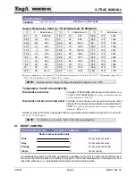
Time (
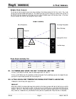
Jumpers
)
Time (
Jumpers
)
Time (
Jumpers
)
Time (
Jumpers
)
0:0 (1111)
0:15 (0111)
0:45 (1011)
1:15 (0011)
1:45 (1101)
2:15 (0101)
2:45 (1001)
3:15 (0001)
3:45 (1110)
4:15 (0110)
4:45 (1010)
5:15 (0010)
5:45 (1100)
6:15 (0100)
6:45 (1000)
7:15 (0000)
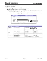
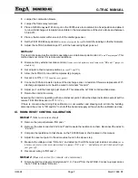
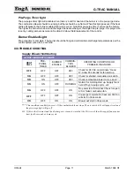
TO SET THE MAINTAIN PURGE TIME DELAY
Maintain Purge Time Delay is set by cutting the “maintain purge” jumpers on the back of the G-TRAC
board. This is best to do before installing a new board. Cut the same jumpers as were cut on the old
board or contact the factory
(after getting unit serial number)
for correct jumper information. Maintain purge
time is determined by the speed that heat exchangers lose heat and control systems react. If purge has
turned off and there is another call for heat, then pre-purge must occur again which may create wide
discharge temperature swings. Turning the combustion fan off is only done as an energy management
step.
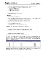
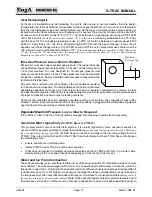
JUMPER CONNECTIONS
APPLICATION
TIME IN
MINUTES
MP-1
MP-2
MP-3
MP-4
ONLY ROOM
CONTROL
0:30
CUT
JUMPER
JUMPER
JUMPER
MOST
APPLICATIONS
6.30
CUT
CUT
CUT
JUMPER
CTRAC
CONTROL
2:30
CUT
CUT
JUMPER
JUMPER
Cutting all MP jumpers allows a "maintain purge" time of 12 minutes
(plus or minus 2 minutes).
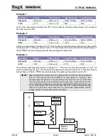
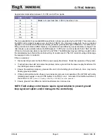
ESTIMATED POT SETTINGS
(Use for situations where design values not available)
If the old G-TRAC is available, there was a sticker inside the cover showing the pot settings as they left
our factory. If this is not available and the control was operating well before it failed, then match the pot
settings. Failing that:
POT 5 Valve Sensitivity
Set at 3
(or slightly lower)
POT 6 Internal Control Band
set at 3
(If G-TRAC is slave to a CTRAC then set this at 4)
POT 8 Burner ON/OFF Control Band
If G-TRAC is slave to a CTRAC then set this at 4
POT 4 Auxiliary Set point
Usually not used. Used only if there is a jumper “SP to
S”
(main set-point)
or “SP to Y”
(reset set-point)
POT 1 Discharge Calibration
Must be set as per instruction in manual
POT 3 Room Calibration
Must be set as per instruction in manual. This is usually
as a room or return air reset rather than as room control.
Used only if V, X, Y, Z are wired
POT 2 Room Reset Ratio
Used only if POT 3 is used. Used to determine how
much authority will be given to the reset
thermostat/sensor. Setting 1 is the minimum authority
(+/- 9ºF)
and setting 5 is the maximum authority
(+/-
32ºF)
.
POT 7 BMS RESET RATIO
Used only if there is a BMS control wired to the BMS
input terminals “+ and –“
(1 is minimum reset authority and
5 is maximum authority)
.
Summary of Contents for G-TRAC 1.1
Page 23: ...IOM 24 Page i March 1999 R1...