5
3903002 06.16
3. MECHANICAL INSTALLATION
3.1 INSTALLATION OF OVER-PRESSURE SWITCH (OPS)
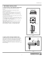
The OPS may be installed in the vertical or horizontal
position.
If mounted horizontally, the set-point knob must face
upwards as shown in Fig. 1.
NOTE: If mounted horizontally, deduct 0.80 inW.C. (20 Pa)
from the setpoint for offset adjustment. Do not use this
mounting arrangement if the setpoint is at the bottom range
of the pressure switch.
If mounted in the vertical position, the pressure ports must be
pointing down as shown in Fig. 1.
Secure the switch by using the mounting holes shown in Fig.
1. Use only two holes located diagonally from each other. Do
not over-tighten the mounting screws.
After installation connect the tubing to the stack probe and
the port marked “P1” and “+”.
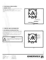
IMPORTANT! REMOVE THE PROTECTIVE CAP ON THE
PORT MARKED “P2” AND “-”. THE SWITCH WILL NOT
WORK PROPERLY UNLESS IT HAS BEEN REMOVED.
3.2 INSTALLATION OF STACK PROBE FOR OPS
Install the stack probe for the OPS in the stack between the
boiler outlet and the damper. The probe must be located so
the distance “A” is at least 3 vent diameters downstream
damper. The probe placement should also observe distances
from elbows and tees as shown in Fig. 2. The tip of the
probe MUST be flush with the inner stack wall to get a proper
pressure reading.
0.80
(200)
0.72
(180)
0.64
(160)
0.56
(140)
0.48
(120)
0.40
(100)
0.32
(80)
0.24
(60)
0.16
(40)
0.08
(20)
in WC
(Pascal)
Typ 930.80
Mounting Holes
+
-
Horizontal Mounting
Vertical Mounting
+
-
Front
Back
Down
IMPORTANT
Remove protective cap!
Tube to
Probe
EXHAUSTO
P1
+
P2
-
+ -
From
Appliance
OPS
MDF, Damper
for MODS system
Probe
Venting to
exterior
A
A
Fig 1
Fig 2

