


13
No maintenance is required except a periodic functional test.
Overheating
When the overheating cut-out with manual reset has been activated, the following should
be observed:
1. The heater must not be interfered with in any way, such as removal of the cover, except
by an authorized electrical fitter.
2. Turn off the mains power.
3. Investigate carefully the reason for activation of the cut-out.
4. When the fault has been eliminated, the cut-out can be reset.
Function description Duct heater for external heating control
• The duct heater is designed for external control via a thyristor type Pulser / TTC or via a
thermostat.
• The heater is equipped with an integral overheating cut-out with manual reset which can
be reset on the outside of the cover.
Wiring diagrams
See chapter “Electrical wiring diagrams”
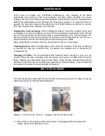
Installation of the temperature sensor
Make a Ø 12 mm hole in the supply air duct 50 cm after the heater (towards the room) and
attach the temperature sensor in the duct using the sensors base. Cabling is drawn,
according to regulations, from the sensor to the Pulser regulator.
Installation of the Pulser regulator
The Pulser regulator is installed according to valid regulations on a mounting box.
MAINTENANCE OF THE DUCT HEATER
Summary of Contents for LTR-3 Series
Page 20: ...20 CHARASTERISTICS...
Page 21: ...21...
Page 22: ...22 WIRING DIAGRAMS...
Page 23: ...23...
Page 24: ...24...
Page 25: ...25...
Page 26: ...26 PLANNING EXAMPLE LTR 3...