


15
IOM, XT Models
Enertech Global
Section 5: Unit Piping Installation
Interior Piping
All interior piping must be sized for proper flow rates
and pressure loss. Insulation should be used on all
inside piping when minimum loop temperatures
are expected to be less than 50°F. Use the table
below for insulation sizes with different pipe sizes.
All pipe insulation should be a closed cell and
have a minimum wall thickness of 3/8”. All piping
insulation should be glued and sealed to prevent
condensation and dripping. Interior piping may
consist of the following materials: HDPE, copper,
brass, or rubber hose (hose kit only). PVC is not
allowed on pressurized systems.
Table 3: Pipe Insulation
Typical Pressurized Flow Center Installation
The flow centers are insulated and contain all
flushing and circulation connections for residential
and light commercial earth loops that require a
flow rate of no more than 20 gpm. 1-1/4” fusion x
1” double o-ring fittings (AGA6PES) are furnished
with the double o-ring flow centers for HDPE
loop constructions. Various fittings are available
for the double o-ring flow centers for different
connections. See figure 6 for connection options.
A typical installation will require the use of a hose
kit. Matching hose kits come with double o-ring
adapters to transition to 1” hose connection.
Note: Threaded flow centers all have 1” FPT
connections. Matching hose kits come with the
AGBA55 adapter needed to transition from 1” FPT to
1” hose.
Piping Material
Insulation Description
1” IPS Hose
1-3/8” ID - 3/8” Wall
1” IPS PE
1-1/4” ID - 3/8” Wall
1-1/4” IPS PE
1-5/8” ID - 3/8” Wall
2” IPS PD
2-1/8” ID - 3/8” Wall
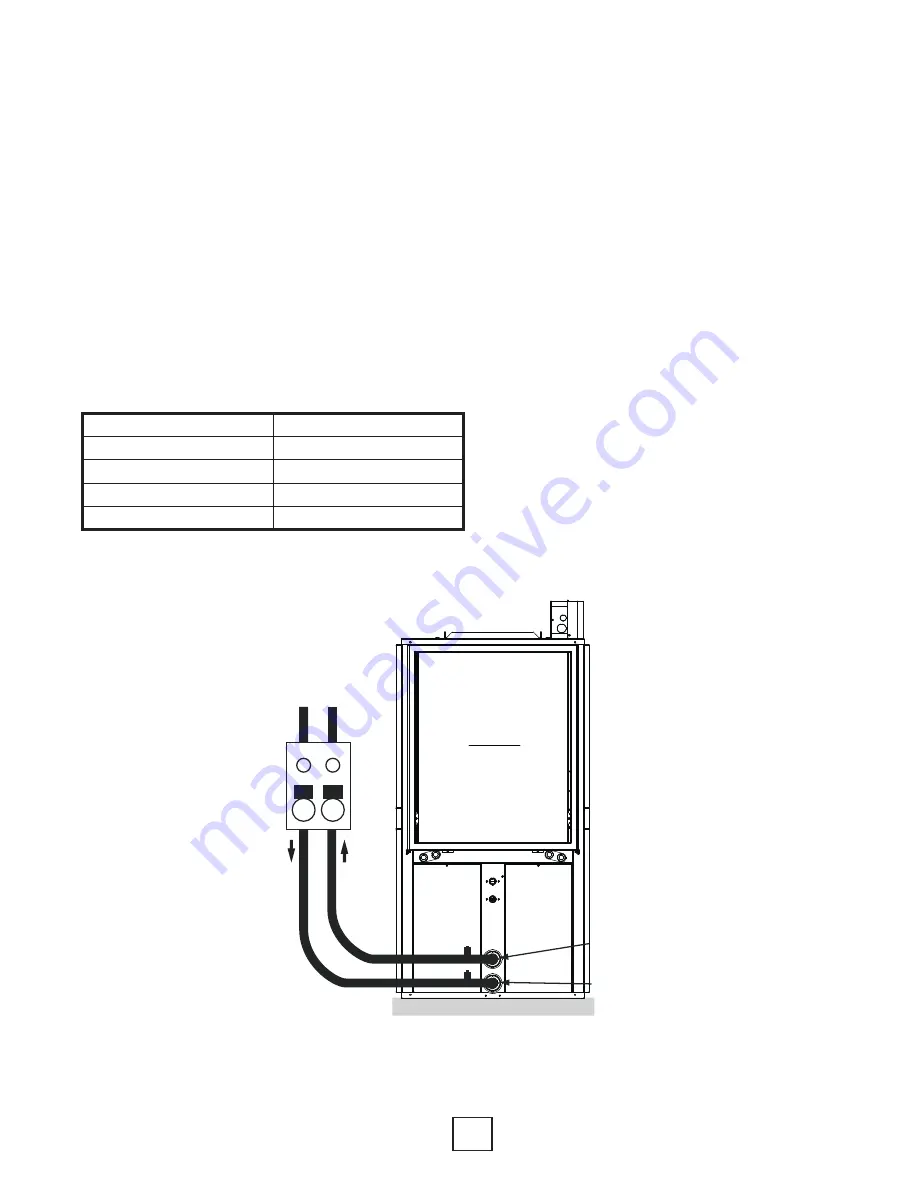
Figure 6: Typical Single Unit Piping Connection (Pressurized Flow Center)
Air Coil
Source Water In
Source Water Out
~
~
Flow
Center
Hose
Kit
To/From
Loop Field
P/T Ports
Equipment Pad
2” Polyethylene Foam
Note: P/T ports should be angled
away from the unit for ease of
gauge reading.