Enertech WD240 Installation & Operation Manual Download Page 13

13

IOM, WD Models

Enertech Global

Features

Enertech Global geothermal heat pump controls leverage a 
modular approach for controlling heat pump operation. The 
control system uses a combination of printed circuit boards, 
depending upon the features equipped in a particular unit. 
This approach simplifies installation and troubleshooting, and 
eliminates features that are not applicable for some units.

Section 7: Controls

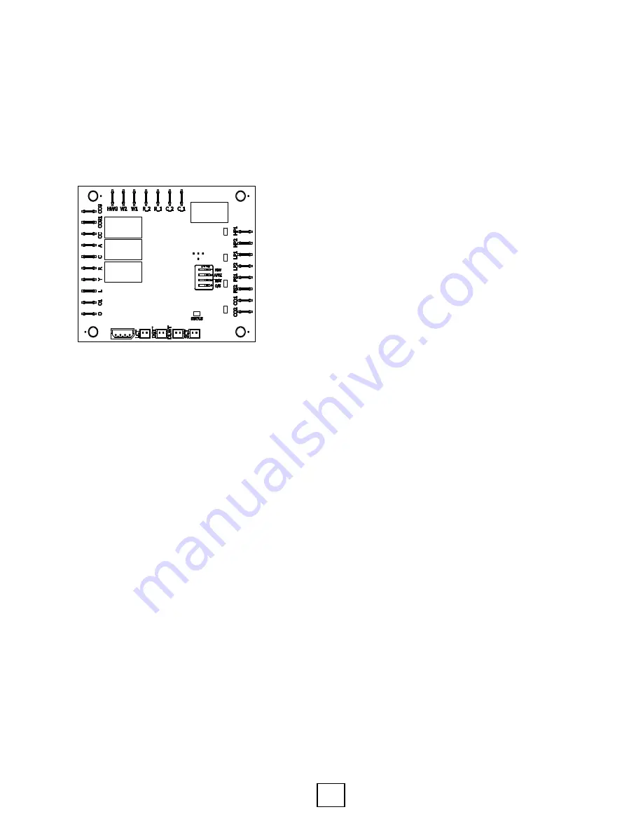
Lockout Board Layout


20D239−01NN

REVISION HISTORY

REV

DESCRIPTION

ECN

DATE

APPROVED

A

INITIAL RELEASE FOR UPDATED CONTROLS 

SECTION IN IOM


4−29−16

KW

GREEN 
HIGH PRESSURE

ORANGE

LOW PRESSURE

RED 

FLOW SWITCH

YELLOW 
CONDENSATE 
OVERFLOW

GREEN 

STATUS

ICM LOCKOUT BOARD

The Lockout Board controls the inputs to the unit as well as 
outputs for current mode, faults, and diagnostics. A status 
LED and different combination of four LEDs for each fault are 
provided for diagnostics. The Lockout Board Terminal (L) puts 
out the number of corresponding 24VAC pulses to indicate the 
Lockout condition on the Thermostat (if equipped and wired).

Startup/Random Start

The unit will not operate until all the inputs and safety controls 
are checked for normal conditions. A ten to twenty second 
random start delay is added at power up and whenever a Y1 
call is received. This avoids multiple units from being energized 
at the same time after events such as power loss or brown 
outs.

Short Cycle Protection

A built-in five minute anti-short cycle (ASC) timer provides 
short cycle protection ensuring that the compressor isn’t 
damaged due to rapid cycling.

Test Mode

The Lockout Board allows the technician to shorten timing 
delays for faster diagnostics by placing the DIP switch ‘TEST’ 
switch in the ON position (See ‘Settings’ section). It should be 
moved back to OFF for normal operation after testing. The 
status LED will not be illuminated during the TEST mode.

4-Way Valve Control

When 24Vac is applied to the O terminal on the field wiring 
block, the controller energizes its O1 output to provide 24Vac 
power to the reversing valve to switch the refrigerant circuit to 
the cooling mode.

Changeover from heating to cooling can be achieved in two 
ways:
1.  A manual toggle switch to select the heating or the 

cooling hydronic control (Aquastat), or. 

2.  A cooling thermostat which powers the coil of a single 

pole/double throw relay to select the heating hydronic 
control (normally closed contact) or the cooling hydronic 
control (normally open contact).

Compressor Control

When 24Vac is applied to the Y terminal on the controller 
wiring block, the controller decides, based on lockout and 
anti-short-cycle periods, when to turn on the compressor 
contactor. The CC output of the controller energizes the 
contactor(s) until 24Vac is removed from the Y terminal or a 
fault is detected.

Safety

The lockout board receives feedback signals for high pressure, 
low pressure, load heat exchanger temperature, source 
heat exchanger temperature, condensate overflow, and 
hot gas temperature faults. Upon a continuous 10-second 
measurement of all faults (except the high pressure) the 
compressor operation is suspended. The high pressure fault is 
tripped instantly. The different combination of LED(s) indicate 
each temporary fault. Once the unit is locked out (see fault 
retry below), the Lockout Board outputs a number of 24VAC 
pulses equal to the numbered fault code.  In lock out the unit 
will not start until a soft or hard reset.

Low Pressure (LP)

If the low pressure switch is open continuously for 10 seconds, 
the compressor operation will be interrupted and the control 
will go into fault retry mode. At startup, the low pressure 
switch monitoring is suspended for 30 seconds to avoid 
nuisance faults.  However, if the low pressure switch is open 
before startup then the unit will not start upon receiving an Y1 
call and will lock out instead.

Note: Flow switches are not equipped with this unit. A jumper 
wire overrides this feature. A flow switch kit is available to add 
on: Part Number: 28K053-05NN.

Flow Switch (FS)

Flow switches ensure the source and load water maintain 
the minimum required flow rate. This ensures that pumps 
are working and water connections remain intact. If the flow 
switch is open continuously for 10 seconds, the compressor 
operation will be interrupted with a FS fault.  At startup, the 
flow switch monitoring is suspended for 30 seconds to avoid 
nuisance faults.  The flow switches will also trip when the 
water begins to freeze, providing additional protection.

Summary of Contents for WD240

Page 1: ...Installation OperationsManual WD 20 30 TON MODELS WATER TO WATER HEAT PUMPS Revision D 20D814 10NN 20D814 10NN...

Page 2: ...10 Section 6 Antifreeze Antifreeze Overview 11 Antifreeze Percentages by Volume 12 Section 7 Controls Features 13 Sequence of Operation 17 Section 8 Wiring Diagrams WD 240 Series WD 240 Series Wiring...

Page 3: ...9 Hot W ater C onfiguration 10 Return Air O ptions 11 Discharge Air O ptions 12 Blow er O ptions 13 Exchanger O ptions 14 15 Standard two stage dual single stage compressors Section 1 Model Nomenclat...

Page 4: ...the unit carefully remove the shrink wrap Using a box cutter slit the shrink wrap on the cardboard top and corner posts Use caution to not damaged the finished surface of the unit Keep all cardboard o...

Page 5: ...Board Logic Board operates the compressor and protects unit by locking out when safety switches are engaged It also provides fault indicator s Terminal Strip Provides connection to the thermostat or...

Page 6: ...ain above 55 F and should be located in a way that piping and ductwork or other permanently installed fixtures do not have to be removed for servicing and filter replacement Electrical All wiring line...

Page 7: ...F 25 F 20 F 15 F 10 F 100 F 110 F 115 F 120 F 125 F 130 F SCROLL COMPRESSOR OPERATING CONDITIONS WATER TO WATER HEATING MODE OPERATION Source Entering Water Temperature 70 F 65 F 60 F 55 F 50 F FAILUR...

Page 8: ...V Physical Dimensions 20 30 Ton Series Model Ground Hydronic Inlet Outlet Inlet Outlet 20 Ton 2 0 MPT 2 0 MPT 2 0 MPT 2 0 MPT 30 Ton 2 0 MPT 2 0 MPT 2 0 MPT 2 0 MPT Physical Data 20 Ton 30 Ton Compres...

Page 9: ...0 0 101 2 113 9 150 7 380 3 173 0 ea 25 0 ea 0 0 0 0 50 0 56 3 80 8 575 3 132 0 ea 23 7 ea 0 0 0 0 47 4 53 3 70 WD240 Model Voltage Code HWG Option 60 Hz OR 50 Hz6 Power Compressor Notes 1 All line a...

Page 10: ...nstallation Potential Problem Chemical s or Condition Range for Copper Heat Exchangers Cupro Nickel Heat Exchanger Ranges Stainless Steel Heat Exchanger Ranges Scaling Calcium Magnesium Carbonate Less...

Page 11: ...des The following are some general observations about the types of brines presently being used Methanol Wood grain alcohol that is considered toxic in pure form It has good heat transfer low viscosity...

Page 12: ...precautions may result in fire injury or death Never work with 100 alcohol solutions Notes 1 Consult with your representative or distributor if you have any questions regarding antifreeze selection or...

Page 13: ...be achieved in two ways 1 A manual toggle switch to select the heating or the cooling hydronic control Aquastat or 2 A cooling thermostat which powers the coil of a single pole double throw relay to...

Page 14: ...mpressor electrical box This module provides advanced diagnostics and protection See chart on next page for Warning and Alert Codes as well as the DIP Switch Settings for these modules Additional info...

Page 15: ...INDICATES THAT THE DISCHARGE GAS TEMPERATURE IS ABOVE 220 F 9 THE L TERMINAL CONTROLS A FAULT LED AT THE THERMOSTAT OR DRIVES AN AUXILLIARY FAULT RELAY 10 UNITS THAT DO NOT CONTAIN A FLOW SWITCH WILL...

Page 16: ...e test mode the LCT SCT sensors will be checked for the proper location based on temperature Sensors are swapped if LCT SCT in cooling or LCT SCT in heating This fault will only show up in the test mo...

Page 17: ...f the two compressors to avoid nuisance low pressure lockouts Heating 1st Stage Y1 The Accessory A terminal output is energized after the random start timer 10s 20s expires to provide time for externa...

Page 18: ...18 Enertech Global IOM WD Models Section 8 Wiring Diagrams WD 240 Series Wiring Diagram...

Page 19: ...19 IOM WD Models Enertech Global Section 8 Wiring Diagrams WD 360 Series Wiring Diagram...

Page 20: ...rce Water Pressure Out Source Water Pressure Drop F F F F F F Heat of Rejection Extraction BTU HR BTU HR F F F F F F Cooling Heating F F F F F F Heating F F F Heating V A GA A Source Water Temp Differ...

Page 21: ...al readings listed in the Unit Electrical Data table 5 Check the source water temperature in and out at the P T ports use insertion probe Allow 10 minutes of operation before recording temperature dro...

Page 22: ...65 3 1 3 2 3 2 3 2 3 1 3 1 3 2 3 5 4 0 3 1 3 1 3 4 3 8 4 4 3 4 3 6 4 0 4 4 5 1 70 3 6 3 7 3 7 3 7 3 6 3 6 3 7 4 0 4 5 3 5 3 6 3 9 4 3 5 0 3 9 4 2 4 5 5 0 5 8 30 0 8 0 8 0 9 1 0 0 9 0 9 1 0 1 0 1 2 0 8...

Page 23: ...mb Antifreeze is generally required for all closed loop geothermal applications Extreme Southern U S locations are the only exception Open loop well water systems cannot use antifreeze and must have e...

Page 24: ...make the project easier to complete ECM Temporary Motor Replacement ECM Motor Troubleshooting Troubleshooting a TXV Compressor Troubleshooting Variable Speed Flow Centers Return Conversion for a XT or...

Page 25: ...loosen pump Take off pump and see if there is an obstruction in the pump If pump is defective replace For pressurized systems check loop pressure Repressurize if necessary May require re flushing if t...

Page 26: ...a sure record the am p s volts suction discharge pressure Y es Y es If the com p ressor still w o n t pum p rep lace com pre ssor A dd re frigerant to the system N o C heck th e opera tion of the reve...

Page 27: ...19 24 19 24 18 22 9 12 Superheat Subcooling Conditions Typical R 410A Unit Superheat Subcooling Values Section 10 Troubleshooting Refrigeration Troubleshooting System Faults Mode Discharge Pressure Su...

Page 28: ...E ____________________ SHIP TO HOMEOWNER ADDRESS Form submitter Ifdifferent than company OTHER NOTES _______________________________________________________________________________ ___________________...

Page 29: ...aller Company Name ________________________________________________________________________________ City _____________________________State Prov __________ Email ______________________________________...

Page 30: ...IOM WD Models Revision Table Date Description of Revision Page WD240 360 Wiring Diagram updated 18 19 06JUL2020 WD 240 360 Rev D Nomenclature added 3 WD 240 360 IOM created ALL Section 11 Warranty Fo...

Page 31: ...31 IOM WD Models Enertech Global This Page Intentionally Left Blank...

Page 32: ...e most up to date information please visit our website or contact our Customer Service department at info enertechgeo com Statements and other information contained herein are not express warranties a...

Reviews: