EnerSys alpha Matrix C16 Technical Manual Download Page 22

22

C048-725-30 Rev. B (01/2020)
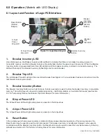
6.2  

6.2  To Inventory the Circuit Breakers

To Inventory the Circuit Breakers

1� 

From the factory, when power is applied to the panel for the first time, the blue Breaker Inventory LED will flash at 

about a one second interval� This indicates that it is necessary to inventory the circuit breakers that are installed in 

the panel� 

2�  Turn on all the circuit breakers that are installed in the panel� Press and hold the Breaker Inventory button� Hold 

the button down until the blue Breaker Inventory LED turns on, then subsequently turns off (about five seconds). 

This indicates that all of the breakers that are installed and turned on have been inventoried and saved to the 

non-volatile memory of the microprocessor� The Breaker Inventory LED will then report the number of inventoried 

breakers by flashing once for each breaker that is installed.


3� 

Check the inventory and the breaker trip indicator function by sequentially turning off each circuit breaker one at 

a time. When a breaker is turned off the red Breaker Trip LED will turn on and the alarm beeper will sound. When 

the breaker is turned back on, the LED will turn off and the alarm beeper will silence.


4�  The breaker inventory will remain in non-volatile memory even if the unit is de-powered� 

5�  If a new breaker is installed at a later date, the red breaker trip LED will turn on, indicating that a new inventory 

must be taken� 

6.3  

6.3  To Temporarily Silence Breaker Trip Alarm Beeper

To Temporarily Silence Breaker Trip Alarm Beeper

1�  To silence the breaker trip alarm beeper, tap the Breaker Inventory button momentarily (press until the blue 

breaker inventory LED turns on, then release)� [Note: the logic PCB only recognizes a momentary tap when the 

breaker inventory button is released after the blue breaker inventory LED has turned on�] 

2�  The breaker trip alarm beeper will silence� 

3�  The breaker trip alarm beeper will re-engage if an additional breaker is tripped, or if the tripped breaker is reset 

and re-trips� 

6.4  

6.4  To Disable/Re-Enable the Breaker Trip Alarm Beeper

To Disable/Re-Enable the Breaker Trip Alarm Beeper

1�  To prevent the breaker trip alarm beeper from sounding on any breaker trip, momentarily tap the breaker inventory 

button (press until the blue breaker inventory LED turns on, then release) four times in a row� 

2�  The breaker trip alarm beeper will not sound when a breaker is tripped� 

3�  To re-enable the breaker trip alarm beeper, repeat step 1� 

6.5  

6.5  To Perform a Factory Reset

To Perform a Factory Reset

1�  To perform a full factory reset (erasing all breaker inventory and alarm settings), hold the breaker inventory button 

and momentarily tap the processor reset button� 

2� 

Continue holding the breaker inventory button until the blue Breaker Inventory LED turns off.


3� 

When the breaker inventory button is released, the blue breaker inventory LED will be flashing, indicating that the 

factory reset was successful�

Summary of Contents for alpha Matrix C16

Page 1: ...Matrix C16 High Density Connectorized DC Distribution Breaker Panel Technical Manual Effective January 2020...

Page 2: ...vides fumes safety information to PREVENT INJURY OR DEATH to the technician or user WARNING FUMES HAZARD FIRE HAZARD WARNING provides flammability safety information to PREVENT INJURY OR DEATH to the...

Page 3: ...stem please contact Alpha Technologies Services Inc or your nearest Alpha representative Alpha shall not be held liable for any damage or injury involving its enclosures power supplies generators batt...

Page 4: ...astic Safety Shields 12 4 5 1 Straight Isolators 12 4 5 2 Optional 90 Degree Isolators 12 4 6 Output Connections 12 4 7 Alarm Installation 13 4 8 Breaker Installation 13 4 9 Installing the Network Cab...

Page 5: ...a Factory Reset 22 7 0 Maintenance Operations 23 7 1 Breaker Removal 23 7 2 Output Connector Removal 23 8 0 Product Specifications 24 9 0 Models and Accessories 25 Appendix A Mechanical Drawings 27 A...

Page 6: ...space to maximize rack space for signal equipment 2 2 2 2 Features Features y Compact 1RU form factor y 400A total rating y 8A and 8B output circuits dual input 16 output circuits single Input y Encl...

Page 7: ...ed for safe operation of the equipment is not compromised 4 1 3 4 1 3 Mechanical Loading Mechanical Loading Mounting of the equipment in the rack should be such that a hazardous condition is not achie...

Page 8: ...ect one of the following sets of mounting ears y For 19 racks use 2 C590 1936 10 y For 23 racks use 2 C590 1937 10 Step 2 Attach the two 2 front mounting ears in the appropriate configuration using th...

Page 9: ...re as shown in Figure 3 and Figure 4 Step 2 Align each rear support rail as shown in Figure 5 Select a hole position for the lacing bar and secure to each rear support rail using the included 10 32 ha...

Page 10: ...ble is required IMPORTANT Grounding hardware not included A properly sized grounding conductor must be installed per NEC 250 122 Table 2 Ground Termination Summary TWO HOLE LANDING TYPE HOLE STUD SIZE...

Page 11: ...TORQUE VALUE Through Hole 3 8in 5 8in 1in 145in lbs 4 4 1 4 4 1 Straight Lug Input Configuration Straight Lug Input Configuration See Figure 9 Step 1 Secure the HOT input cables lug s to the HOT input...

Page 12: ...nput bus bars on the panel 4 5 2 4 5 2 Optional 90 Degree Isolators Optional 90 Degree Isolators Step 1 Place the bottom portion of the isolator on the bottom of the input bus assembly and align with...

Page 13: ...ARRY A UL 489 RATING AT THIS TIME NOTICE MAKE SURE CIRCUIT BREAKERS ARE IN THE OFF POSITION PRIOR TO INSTALLATION ENSURE CIRCUIT BREAKERS ARE COMPLETELY INSERTED CAUTION There are 16 breaker positions...

Page 14: ...ct a laptop directly to the Ethernet port of the Matrix panel If the laptop is configured for Auto MDI X a straight through cable may be used Step 1 Connect a Cat 5 5e 6 UTP Ethernet cable from the lo...

Page 15: ...the SmartSwitch for at least 3 seconds 5 2 5 2 Home Screen Information Home Screen Information The SmartSwitch home screen displays Input bus voltage input bus current and alarm status Under normal o...

Page 16: ...for 3 seconds to continue Step 5 The SmartSwitch will now display STORED PRESS TO CONT Tap the SmartSwitch to continue and set the breaker ampacity 5 3 2 5 3 2 Setting Breaker Ampacity Setting Breaker...

Page 17: ...rent monitoring features Step 1 To set the bus A ampacity select the option that says SETUP BUS A HOLD 3 S The SmartSwitch will then display HOLD TO EDIT TAP TO SHIFT Tap to access the first bus Step...

Page 18: ...have an Ethernet web server but you would like to add one or if you are unsure if this option is installed on your panel contact Alpha Support The optional embedded Ethernet module provides remote mon...

Page 19: ...atrix Ethernet web server using the link located at the bottom of the Administration Settings page Notification Settings Allows a user to edit settings for SNMP traps or email alerts All remote alarms...

Page 20: ...D 3S OF BREAKERS CORRECT EXIT HOLD 3S SETUP BUS ALMS SETUP RATING HOLD 3S EXIT HOLD 3S SETUP BKR ALRMS ALARM WARNING EXIT HOLD 3S SETUP ADVANCED RESTORE DEFAULTS SETUP DEMO SYSTEM INFO EXIT HOLD 3S Ab...

Page 21: ...for more than five seconds is used to store the breaker inventory in nonvolatile memory The button may also be used to temporarily silence indefinitely disable or re enable the beeper see Section 6 3...

Page 22: ...n on indicating that a new inventory must be taken 6 3 6 3 To Temporarily Silence Breaker Trip Alarm Beeper To Temporarily Silence Breaker Trip Alarm Beeper 1 To silence the breaker trip alarm beeper...

Page 23: ...to the breaker There are threaded inserts on the face of the breaker for this purpose see Figure 19 Step 4 Pull the breaker straight out from the front of the panel see Figure 20 Step 5 Reinstall the...

Page 24: ...A max continuous Total Load Current 320A max continuous Alarm Contacts Form C 60VDC 0 5A max Circuits Up to 16 Maximum Input Interruption Device 400A Mechanical Dimensions L x H x D 17 x 1 75 x 16 5 W...

Page 25: ...t Dual Input C750 171 10 Matrix C16 Rear Mount Support Kit w Adjustable Lacing Bar C750 284 10 Table 10 Replacement Parts DESCRIPTION PART NUMBER SmartSwitch Supervisory Controller C016 1621 10 and C0...

Page 26: ...r C745 233 10 Blue Blue Tracer C745 234 10 10 7 Red Black C745 402 10 Blue Black C745 408 10 Red Red Tracer C745 411 10 Blue Blue Tracer C745 415 10 12 Red Black C745 375 10 Blue Black C745 380 10 Red...

Page 27: ...48 725 30 Rev B 01 2020 Appendix A Appendix A Mechanical Drawings Mechanical Drawings A 1 A 1 Single Input Matrix C16 C016 1621 10 Single Input Matrix C16 C016 1621 10 w o Safety Shields w o Safety Sh...

Page 28: ...28 C048 725 30 Rev B 01 2020 A 2 A 2 Single Input Matrix C16 Single Input Matrix C16 C016 1621 10 C016 1621 10 w Straight and 90 Degree Safety Shields w Straight and 90 Degree Safety Shields...

Page 29: ...29 C048 725 30 Rev B 01 2020 A 3 A 3 Dual Input Matrix C16 C016 1622 10 Dual Input Matrix C16 C016 1622 10 w o Safety Shields w o Safety Shields...

Page 30: ...30 C048 725 30 Rev B 01 2020 A 4 A 4 Dual Input Matrix C16 Dual Input Matrix C16 C016 1622 10 C016 1622 10 w Straight and 90 Degree Safety Shields w Straight and 90 Degree Safety Shields...

Page 31: ......

Page 32: ...60 Technical Support 1 800 863 3364 For more information visit our website at www alpha com 2020 Alpha Technologies Services Inc All Rights Reserved Trademarks and logos are the property of Alpha Tech...

Reviews: