


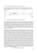


6. System Mounting Instructions
A pair of rack mount brackets are included with the CU-12 (38), unscrew the side screws (39), then
fasten the brackets with these screws and put the CU-12 in the rack, finally install the unit onto the rack
with 4 screws (40).
7.
Limited Warranty Statement
Enersound warrants its Interpretation System: CU-12, IC-12 to be free from defects in workmanship and
material under normal use and conditions for one year from the date of purchase from an authorized
dealer. All other products and accessories are warranted for 90 days from date of purchase. This warranty
is only available to the original end purchaser of the product and cannot be transferred. If the product is
determined to be defective, Enersound will repair or replace it, at its discretion, at no charge. Customer
must pay for shipping. This warranty is void if damage occurred because of misuse or if the product has
been repaired or modified by anyone other than a factory-authorized service technician. Warranty does
not cover normal wear and tear on the product or any other physical damage unless the damage was the
result of a manufacturing defect.
Enersound has no control over the conditions under which this product is used. Therefore, the company
disclaims all warranties not set forth above, both express and implied, with respect to the Interpretation
System, including but not limited to any implied warranty of merchantability or fitness for a particular
purpose. Enersound products manufacturer, distributors and/or dealers shall not be liable to any person
or entity for any medical expenses or any direct, incidental or consequential damages caused by any use,
defect, failure or malfunction of the product, whether a claim for such damages is based upon warranty,
contract, tort or otherwise. The sole remedy for any defect, failure or malfunction of the product is
replacement of the product. No person has any authority to bind Enersound to any representation or
warranty with respect to the Enersound Interpretation System. This warranty gives you specific legal
rights, and you may also have other rights which vary from state to state. Some states do not allow
limitations on how long an implied warranty lasts, and the exclusion or limitation of incidental or
consequential damages, so the above limitation may not apply to you. This warranty applies to products
sold only within the United States of America and does not cover products sold AS IS or WITH ALL
FAULTS. For products sold outside the U.S., please consult with your local dealer about the terms and
conditions applicable in your country. Proof of purchase in the form of a bill of sale, invoice number or
receipted invoice, which is evidence that the unit is within the warranty period, must be presented to
obtain warranty service. If you experience difficulty with your interpretation System, send an email to
[email protected] with your name, address, phone number and a complete description of the
problem. We will respond to you as soon as possible and if it is necessary to return the product for service,
your Customer Service Representative will give you a Return Authorization Number (RAN) and shipping
instructions. For more information, visit www.enersound.com. You may also call 1-305-731-2416 or our
toll-free number 1-800-644-5090 within the U.S.
©2013 Enersound. All rights reserved.
11


