


8
RSL Torque Wrench
3.2.12 RSL Features and Accessories [continued]:
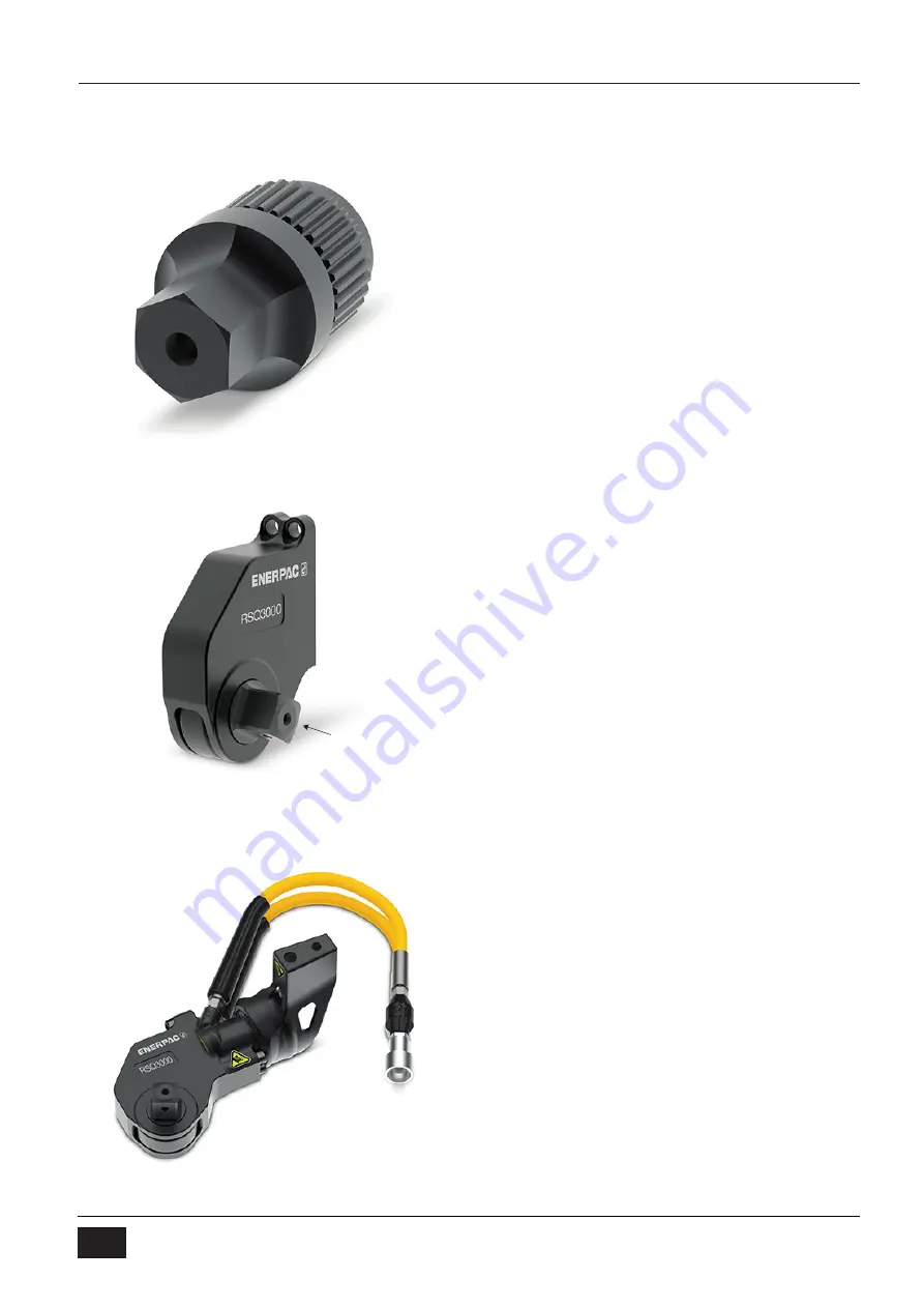
g.
Hex Bit
h. Square Drive Cassette (RSQxxxxx)
i. Square Drive Torque Wrench Set
(RSQxxxxxST)
Square Drive
4 Operation Instructions
4.1 Flange Assembly and Disassembly
4.1.1 Perform hazard analysis before starting
work.
4.1.2 Ensure fastener contact surfaces and
flanges have been properly cleaned and
examined.
a. Flanges:
i. Surface finish, scratches, nicks, burrs,
flatness.
ii. Nut bearing surface – No paint or other
thick coating, not scored.
b. Fasteners:
i. No rust, corrosion, burrs.
ii. Make sure bolt/nut will turn freely by
hand beyond position where it will come
to rest. Do not lubricate for this test.
iii. Fastener replacement is always the safe
option.
iv. See ASME PCC-1-2013 for fastener
replacement guidelines.
4.1.3 Ensure:
a. Joint members are properly aligned.
b. Gasket is properly installed.
c. Lubrication of fastener working surfaces
have been properly considered.
4.2 Choose Flange Assembly Method
4.2.1 TIGHTENING METHOD 1 – Follow
equipment manufacturer procedures.
4.2.2 TIGHTENING METHOD 2 – Torque using
Legacy Cross-Pattern Tightening Sequence
and Bolt Numbering (Table 4.2-1). Single
tool 8 bolt flange example - Fig. 4.2-1:
a. Mark fasteners with chalk in clockwise
direction (1, 2, 3, 4, 5, 6, 7, and 8).
These numbers are outside large circle
in Fig. 4.2-1 (e.g. 1-5-3-7-2-6-4-8).
b.
Mark correct tightening sequence on
studs (“1”, “2”, “3”, “4”, “5”, “6”, “7”, and
8”).
i. This sequence is 1-5-3-7-2-6-4-8.
ii. These are the “circled numbers” in
Fig 4.2-1.
iii. In this case, “1” relates to 1, “2” to 5, “3”
to 3, “4” to 7, “5” to 2, “6” to 6, “7” to 4,
and “8” to 8.
c. Determine torque value for each stage of
stud tightening.
i. First stage - limit to 30% of final torque.
ii. Second stage - limit to 60% of final
torque.
iii. Third and Fourth stages - 100% of final
torque.