4
①
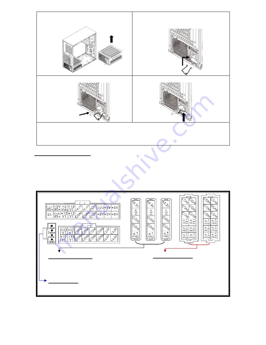
Set your PSU into the bottom chassis
(main air frame should face up), and please
make sure the I/O switch is on “O” position.
②
Press two sides of the CordGuard lock
together, and set it into CordGuard holder
near the AC inlet.
③
Plug the AC cord into your PSU.
④
Lock the CordGuard to latch onto AC
cord.
1. CordGuard is for AC cords supplied with ENERMAX CordGuard-compatible PSUs. Other
AC cords may be incompatible.
2. When assembling or maintaining the system, please remove AC cord from AC inlet, or
turn I/O switch into “O” position.
CABLES & CONNECTORS
All connectors are designed to prevent insertion in wrong orientation. If you cannot easily insert a
connector, please check if you are inserting the connector in the right orientation. Do not try by
force to insert it nor modify the connectors. This might damage power supply and system
components, and warranty shall be void.
Following graphic illustrates the modular sockets layout and its DC rail distribution.
The black sockets provide 3.3V/5V/12V for
modular cable to power drives or other
peripheral.
The red sockets provide 12V for
modular cable to power graphics
card, CPU/GPU or RAM.
This port provides digital signal to MB’s USB port for further software control.
Please refer to ZDPMS manual for more detail.
* You must connect 16-pin and 20-pin connectors into respective sockets to enable 24-pin MB and 8-pin
CPU connectors.
* This product incorporates multiple 12V rails over current protection. If you let many peripherals consume
the power on only one 12V rail, it may trigger the over current protection and shut down the system.
Please re-direct certain peripheral power cable to other 12V rail to share the current loading to ensure
highest stability and safety.
5P BLACK sockets
12P RED sockets
(this side up)
ZDPMS port:


