Energy Tech Laboratories MR212 Installation, Operation And Maintenance Manual Download Page 16


16

Flame Safety Controller 
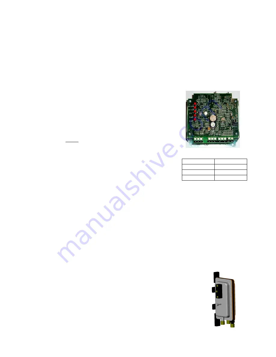
 

Air Flow Switch 

DC Flame Signal 

DC Voltage 

Flame Status 

0 to 5 VDC 

No Flame 

6 to 11 VDC 

Weak Flame 

12 to 18 VDC  Strong Flame 

Sequence of Operation 

The direct-fired heater is most easily understood when broken down into smaller individual systems. 
There are two main systems, a make-up air fan and a heater. The make-up air fan consists of a blower 
and motor. The heater may be further broken down into two control systems, the Flame Safety Control 
(FSC) and the Modulating Gas System (MGS). The burner mixes air with the gas (Natural or LP) which 
heats the air. 

Flame Safety Control


The first system to understand is the 

Flame Safety


Control

. The FSC 

is there 

only


to monitor the flame, NOT to control temperature. The 

FSC uses a flame rectification sensor mounted on the pilot assembly 
to detect the presence of flame in the burner.  Flame strength and 
presence can be measured at the FSC by reading the rectified flame 
signal.  This is done by using a DC voltage meter attached to the test 
jacks on the top of the control.  Flame is present when the DC voltage 
reads between 

6 and 18 VDC

.  Ideal flame intensity produces a signal 

of 

12 VDC

 or greater.  The FSC is also wired into an airflow switch, 

which tells it whether there is proper airflow through the unit (not 

just 

any airflow, but 

proper

 airflow). Proper airflow occurs when there is a 

.15 in. w.c. to .80 in. w.c. differential pressure drop across the 
burner

.   When the airflow through the heater produces a pressure 

drop in this range, the FSC indicates so by illuminating the AIRFLOW 
LED.  The FSC controls the opening of the redundant solenoid gas 
valves and the operation of the spark igniter to initiate a pilot flame 
upon start-up. 
 
The 

OPR CTRL

 LED indicates that there is power to the FSC. Next, 

the 

AIRFLOW

 LED will come on if there is proper airflow through the 

unit.  Third, the unit will pause to purge any gasses or combustible vapors before attempting flame 
ignition. Then, there is a Pilot Trial For Ignition (PTFI) and the 

PTFI

 LED comes on. During PTFI, the FSC 

opens the pilot gas valve and allows gas to flow to the pilot assembly.  At the same moment, the spark 
igniter is started, causing the spark to ignite the pilot gas.  When the flamerod sensor detects the flame, it 
turns on the 

FLAME

 LED, turns off the PTFI LED, and powers the modulating gas system.  This is the 

normal operating mode. The FSC continues to monitor the flame and airflow.  Once this occurs, the unit is 
in a main flame cycle and thus powers the main gas valve and the modulating gas system.  This is the 
normal operating mode. The FSC continues to monitor the flame and airflow.  The last LED on the FSC is 
the 

ALARM

 LED.  This will turn on when the FSC determines an unsafe condition has occurred, and will 

not allow the unit to recycle for heat until it has been properly reset.  Anytime the FSC has gone into 
“Alarm” mode, the problem must be diagnosed and corrected to avoid future lockouts after resetting.  To 
begin troubleshooting, or to reset the FSC, shut down power to the heater and restart the heater.  This 
will clear the alarm from the flame safety. 

Air Flow Switch


There are both high and low 

airflow switches 

contained within one housing 

measuring the pressure drop across the burner.  This is to insure that there is 
proper airflow 

(.15 in. w.c. to .80 in. w.c.

) across the burner and proper 

combustion at all times.  Both switches are wired in series and have single pole 
double throw (one common contact, one normally open contact, and one normally 
closed contact) switches that are ‘switched’ by air pressure. There are two airflow 
tubes in the heater, located near the burner and profile plate assembly (profile 
plates surround the burner and control air into the burner section).  In the case of 
clogged filters, blocked intake, excessive duct static pressure, or a broken belt, the 
correct burner differential pressure may not be achieved, not allowing the low 

Summary of Contents for MR212

Page 1: ...D INSPECTION Upon receiving unit check for any interior and exterior damage and if found report it immediately to the carrier Also check that all accessory items are accounted for and are damage free Turn the blower wheel by hand to verify free rotation and check the damper if supplied for free operation WARNING Improper installation adjustment alteration service or maintenance can cause property ...

Page 2: ......

Page 3: ...tart Up Procedure 14 Pulley Adjustment 14 Pulley Alignment 14 Proper Belt Tension 14 Pulley Combination Chart 15 Sequence of Operation 16 Flame Safety Control 16 Air Flow Switch 16 Modulating Gas System 17 High Temperature Limit 17 Operation Summary 17 Optional Remote Panel Circuit 18 Components 19 Remote Panel Option 20 Troubleshooting 21 Airflow Troubleshooting Chart 21 Burner Troubleshooting Ch...

Page 4: ...capacity 5 The invoice is not paid within the terms of the sales agreement The MANUFACTURER shall not be liable for incidental and consequential losses and damages potentially attributable to malfunctioning equipment Should any part of the equipment prove to be defective in material or workmanship within the 12 month warranty period upon examination by the MANUFACTURER such part will be repaired o...

Page 5: ...following procedure to assemble the intake to the heater 1 Apply silicone or weather proof gasket on the back side of the flanges of the intake hood or v bank intake 2 Screw the flanges of the intake hood or v bank to the unit with the supplied sheet metal screws If the unit is a modular unit with a v bank or evaporative cooler section the v bank or evaporative cooler will bolt to the heater with ...

Page 6: ...hods the structure s designed infiltration rate by providing properly sized relief openings or by interlocking a powered exhaust system or by a combination of these methods Heaters installed with intake ductwork must be purged to replace at least four air changes of the volume of the intake duct If the failure or malfunction of this heater creates a hazard to other fuel burning equipment in the bu...

Page 7: ...and the blower module 3 Support and level the end of the heat module end opposite the blower with the provided equipment legs rails 4 Attach the filter hood to the intake side of the heater module 5 Drill a hole in the discharge of the blower large enough to insert the Maxitrol mixing tube and discharge sensor if provided Install the Maxitrol mixing tube in the proper airflow direction The airflow...

Page 8: ...es 4 Install a ground joint union with brass seat and a manual shut off valve external to the unit casing as shown below adjacent to the unit for emergency shut off and easy servicing of controls 5 Provide a sediment trap as shown below before each unit and where low spots in the pipe line cannot be avoided 6 Blow out the gas line to remove debris before making connections Purge line to remove air...

Page 9: ...to Building Wiring Connection 4 Make certain that the power source is compatible with the requirements of your equipment The heater nameplate identifies the proper phase and voltage of the motor 5 Units shipped with an optional remote panel have two electrical circuit drops It is important to run the motor wires in a separate conduit from the remote control wiring The DC wires from the unit temper...

Page 10: ...heater There is a terminal strip inside the remote panel that matches the terminals in the heater unit The remote panel should be wired as shown below BL YW RD BK PK RD WH OR BR GY BK RD YW PK RD BK WH BK OR BR GY PK RD BK YW RD OR BR GY WH BK 1 E PK YW BK RD WH GY BR OR RD NC BK Fire System Microswitch BK NO PR C Fan to Building Wiring Connection ...

Page 11: ...For 3 phase motors any two power leads can be interchanged to reverse motor direction 7 When the fan is started up observe the operation and check for any unusual noises Pilot Adjustment 1 Restart the fan and check the gas supply pressure at the inlet gas tap upstream of all electronic valves The inlet pressure should be 7 in 14 in w c 7 in w c 5 psi on Size 4 5 heaters If the inlet pressure is to...

Page 12: ...the combination gas valve regulator adjustment size 1 3 or the cap from the MR212 valve size 4 5 Using the regulator pressure adjusting screw adjust the high fire manifold pressure to 5 in w c maximum for natural gas and 2 5 in w c maximum for propane gas High fire should be set to generate the desired temperature rise If the high fire screw is at the end of its adjustment and more pressure is nee...

Page 13: ...Maxitrol 44 This will drive the valve into its full open position Adjust high fire with the regulator inside the unit Turn clockwise to increase temperature rise Ensure that DC flame signal is minimum 12 VDC Replace the wires on the Maxitrol Amplifier Adjusting low fire Remove wire 5 from the Maxitrol 14 amplifier 8 for Maxitrol 44 This will drive the valve into its lowest position Adjust the low ...

Page 14: ... not set fan RPMs higher than specified in the maximum RPM chart See the troubleshooting guide for more information 3 Measure and record the voltage and amperage to the motor and compare with the motor nameplate to determine if the motor is operating under safe load condition 4 Once the rpm of the ventilator has been properly set disconnect power and recheck belt tension and pulley alignment as de...

Page 15: ... 1165 1187 1210 1232 1255 1277 1299 1322 3 to 5 HP MOTOR PULLEY Dd1 Dd2 Pd1 Pd2 BX BELTS 2VP42 2 9 3 9 3 4 Open Closed BLOWER PULLEY DATUM DIAMETER PITCH DIAMETER 6 5 1 2 5 4 1 2 4 3 1 2 3 2 1 2 2 1 1 2 1 1 2 0 2B5V278 27 8 28 1 184 189 194 200 205 210 215 220 225 230 235 240 246 2B5V250 25 25 3 205 210 216 222 227 233 239 244 250 256 261 267 273 2B5V234 23 4 23 7 218 224 230 237 243 249 255 261 2...

Page 16: ...rd the unit will pause to purge any gasses or combustible vapors before attempting flame ignition Then there is a Pilot Trial For Ignition PTFI and the PTFI LED comes on During PTFI the FSC opens the pilot gas valve and allows gas to flow to the pilot assembly At the same moment the spark igniter is started causing the spark to ignite the pilot gas When the flamerod sensor detects the flame it tur...

Page 17: ...as system consists of a temperature selector dial a discharge air sensor an amplifier and a modulating gas valve The two types of Maxitrol systems used are the Maxitrol 14 series or the Maxitrol 44 series The Maxitrol 14 utilizes a discharge air sensor and modulates the Maxitrol gas valve to provide discharge air to match the selected temperature on the temperature selector The Maxitrol 44 utilize...

Page 18: ...itch Nothing Happens No Power is Sent to Heater Power is Sent to Heater to Open Damper if provided and Start Blower Off Position 3 Position Panels Only Manual Blower On Light Damper is not Open or Freeze Stat has Detected Low Temperature Operation On Off Temperature Control Switch Blower Operates Heat Does not Operate Vent Position Heat Position Heat Circuit is Energized Burner On Light Illuminate...

Page 19: ...sed to provide 120V service to controls 11 Circuit Breaker Protects electrical components from high current spikes 12 Terminal Strip Central location to terminate control wiring Should be used for troubleshooting 13 Control Transformer 120V primary 24V secondary control transformer 14 Low Pressure Airflow Probe Measures profile pressure downstream of burner 15 High Pressure Airflow Probe Measures ...

Page 20: ...t Vent Switch This switch is powered when the Manual Off Auto switch is in the MANUAL position It is used to control the tempering mode of the unit The VENT position will prevent the burner from operating and the heater will deliver untempered air The HEAT position will force the burner on and the unit will heat the incoming air This switch becomes a Heat Vent Cool switch when the cooling interloc...

Page 21: ...o low Determine if HP is sufficient for job Duct static pressure lower than design Reduce fan RPM Insufficient Airflow Fan rotating in the wrong direction Be sure fan is rotating in the direction shown on rotation label Poor outlet conditions There should be a straight clear duct at the outlet Intake damper not fully open Inspect damper linkage and replace damper motor if needed Duct static pressu...

Page 22: ...Check wiring to valve Defective pilot sensor Replace pilot sensor Shut off valve closed Open shut off valve Defective flame safety controller Replace flame safety controller Pilot fails as main gas valves open and main gas begins to flow Plug the first burner port next to the pilot gas tube with burner cement Not Enough Heat Main gas pressure too low Increase main gas pressure do not exceed 14 in ...

Page 23: ... Panels Only Heat Vent Switch in Vent Position Gas Pressure Switch Tripped option High Temperature Limit Thermostat Tripped Manual Off Auto Switch in Auto Position and Intake Air Thermostat not Satisfied Improper Airflow Insufficient Airflow Excessive Airflow Bad airflow switch Problem with air probes Problem with airflow tubing Broken Belt POWER Light and BLOWER ON Light and BURNER ON Light Prope...

Page 24: ...ifier is there 9 5K to 11K Ohms between the wires Replace Discharge Air Sensor Remove Terminal 4 from the Maxitrol Amplifier Does the heater go into High Fire Replace Amplifier With wires 1 2 removed from the Maxitrol Amplifier is there 9 5K to 11K Ohms between the wires Replace the Temperature Selector Is there a short or open circuit in Modulating Valve Should be 45 55 Ohms 60 80 on MR212 Replac...

Page 25: ...injury 3 All fasteners should be checked for tightness each time maintenance checks are preformed prior to restarting unit 4 Blowers require very little attention when moving clean air Occasionally oil and dust may accumulate causing imbalance If the fan is installed in a corrosive or dirty atmosphere periodically inspect and clean the wheel inlet and other moving parts to ensure smooth and safe o...

Page 26: ...d be checked for tightness each time maintenance checks are preformed prior to restarting unit Every 3 months 1 Belt tension should be checked quarterly See instructions in the previous maintenance section Over tightening will cause excessive bearing wear and noise Too little tension will cause slippage at startup and uneven wear 2 Filters need to be cleaned and or replaced quarterly and more ofte...

Page 27: ...27 ...

Page 28: ...e Serial Number Motor Amperage Motor Volts RPM Motor Hertz Burner Differential Pressure in w c Motor Phase Pilot Flame Signal VDC Motor FLA Low Fire Flame Signal VDC Motor HP High Fire Flame Signal VDC Blower Pulley Gas Type Motor Pulley High Fire Inlet Gas Pressure in w c Belt Number Low Fire Manifold Gas Pressure in w c Gas Type High Fire Manifold Gas Pressure in w c Min Btu Hr Thermostat Set Po...

Reviews: