background image

Liquipoint FTW33

Description of Device Parameters

Hauser

35

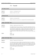
Device search

Navigation

Diagnosis → Device search

Description

This parameter is used to uniquely identify the device during installation.

The green LED is lit (= operational) on the device and starts to flash with increased lumi-

nosity, flash frequency 

.

Note

There is no external signaling via LEDs on the metal housing cover (IP69).

Options

• OFF

• ON

Factory setting

OFF

Sensor check

Navigation

Diagnosis → Sensor check

Description

This parameter is used to test if the measuring point is functioning correctly.

The sensor must not be covered and must be free of residue. The device compares the cur-

rent measured values with the measured values from the factory calibration.

The device must be removed before the sensor check since the free value is influ-

enced by the type of installation.

Options

Check: Following the test, one of the following messages is displayed:

• Message (0x1814) for sensor check passed

• Message C103 (0x1813) for sensor check failed

Summary of Contents for Liquipoint FTW33

Page 1: ...Products Solutions Services Operating Instructions Liquipoint FTW33 Conductive and capacitance point level measurement BA01902F 00 EN 01 18 71423738 2018 06 29 ...

Page 2: ...Liquipoint FTW33 2 Endress Hauser Order code Ext ord cd Ser no www endress com deviceviewer Endress Hauser Operations App XXXXXXXXXXXX XXXXX XXXXXX XXX XXXX XX Serial number 1 3 2 A0023555 ...

Page 3: ...st magnet 18 7 3 Operation via IO Link operating menu 18 8 Overview of the operating menu 20 9 System integration 21 9 1 Process data 21 9 2 Reading out and writing device data ISDU Indexed Service Data Unit 21 10 Commissioning 24 10 1 Function check 24 10 2 Commissioning the local display 24 10 3 Commissioning with an operating menu 25 11 Operation 26 11 1 Customer specific IO Link settings 26 11...

Page 4: ... situation can result in minor or medium injury DANGER This symbol alerts you to a dangerous situation Failure to avoid this situation will result in serious or fatal injury NOTICE This symbol contains information on procedures and other facts which do not result in personal injury WARNING This symbol alerts you to a dangerous situation Failure to avoid this situation can result in serious or fata...

Page 5: ... www endress com deviceviewer Enter the serial number from nameplate Endress Hauser Operations App Enter the serial number from the nameplate or scan the 2D matrix code QR code on the nameplate 1 3 1 Technical Information TI Planning aid The document contains all the technical data on the device and provides an overview of the accessories and other products that can be ordered for the device 1 3 2...

Page 6: ...gistered trademark It may only be used in conjunction with products and services by members of the IO Link Community or by non members who hold an appropriate license For more detailed information on the use of IO Link please refer to the rules of the IO Link Community at www io link com ...

Page 7: ...at the measuring device remains in proper condition for the operating time Use the device only for media to which the process wetted materials are sufficiently resistant Observe the limit values in Technical data Incorrect use The manufacturer is not liable for damage caused by improper or non designated use Verification for borderline cases For special fluids and media used for cleaning the manuf...

Page 8: ... repair of an electrical device Use original spare parts and accessories from the manufacturer only Hazardous area To eliminate a danger for persons or for the facility when the device is used in the hazardous area e g explosion protection pressure vessel safety Based on the nameplate check whether the ordered device is permitted for the intended use in the hazardous area Observe the specification...

Page 9: ... and pastes to be used preferably in pipes and in storage mixing and process vessels with or without an agitator for flush mounted installation 3 1 Product design 1 3 4 5 6 2 A0036957 1 Product design 1 M12 plug 2 Plastic housing cover IP65 67 3 Metal housing cover IP66 68 69 4 Housing 5 Process connection 6 Sensor ...

Page 10: ...he identification of the measuring device Nameplate specifications Extended order code with breakdown of the device features on the delivery note Enter the serial number from the nameplates into W M Device Viewer www endress com deviceviewer All the information about the measuring device and the scope of the associated Technical Documentation are displayed Enter the serial number from the nameplat...

Page 11: ...re 10 Ambient temperature range 11 Process pressure 12 Certificate symbols communication mode optional 13 Degree of protection e g IP NEMA 14 Certificate and approval relevant data 15 Measuring point identification optional 16 Manufacturing date year month 17 2 D matrix code QR code 18 Document number of Operating Instructions 4 5 Storage Transport 4 5 1 Storage conditions Permitted storage temper...

Page 12: ... 1 2 3 A0036961 2 Installation examples 1 Overfill prevention or upper level detection maximum safety 2 Dry running protection for pump minimum safety 3 Lower level detection minimum safety 5 1 2 Installation in pipes A0021052 3 Mounting position in horizontal pipes A0038773 4 The measurement can be impaired if the sensor is partially covered or if air bubbles occur at the sensor ...

Page 13: ...nnection 5 2 Installing the device 5 2 1 Required tools Open ended wrench or for measuring points that are difficult to access a hexagon tubular socket wrench 32 mm 1 When screwing in turn by the hex bolt only Torque 15 to 30 Nm 11 to 22 lbf ft 5 2 2 Installation A B C 32 mm 32 mm 32 mm A0021389 A Thread G B Thread G G 1 C Thread M24 1 5 5 3 Post installation check Is the device undamaged visual i...

Page 14: ...int identification and labeling correct visual inspection Is the device adequately protected against precipitation and direct sunlight Is the device adequately protected against impact Are all mounting and safety screws securely tightened Is the device properly secured ...

Page 15: ...f the power fails quiescent current principle IO Link Communication on pin 4 switch mode on pin 2 SIO mode If there is no communication the device switches to the SIO mode standard IO mode The functions configured in the factory for the MAX and MIN modes can be changed via IO Link HNO HNC hysteresis 6 2 Supply voltage SIO mode 10 to 30 VDC IO Link mode 18 to 30 VDC IO Link communication is guarant...

Page 16: ...ment MAX output LED yellow ye 2 2 1 3 4 ye2 2 2 Function monitoring When both outputs are connected the MIN and MAX outputs assume opposite states XOR when the device is operating fault free In the event of an alarm condition or a cable break both outputs are de energized This means that function monitoring is possible in addition to level monitoring The behavior of the switch outputs can be confi...

Page 17: ...nment MAX output LED yel low ye 2 MIN output LED yel low ye 1 LED red rd 2 4 2 4 6 4 Post connection check Are the device and cable undamaged visual inspection Does the supply voltage match the specifications on the nameplate If supply voltage is present is the green LED lit With IO Link communication is the green LED flashing ...

Page 18: ...t directly at the machine by means of a test magnet 7 3 Operation via IO Link operating menu 7 3 1 IO Link information IO Link is a point to point connection for communication between the device and an IO Link master This requires an IO Link compatible module IO Link master for operation The IO Link communication interface enables direct access to the process and diagnostic data It also provides t...

Page 19: ...ion options Endress Hauser 19 7 3 2 IO Link download http www endress com download Select Software as the media type Select Device Driver as the software type Select IO Link IODD In the Text Search field enter the device name ...

Page 20: ...ic LST 34 Simulation Switch Output OU1 34 Simulation Switch Output OU2 34 Device search 35 Sensor check 35 Parameter Application Active switchpoints 36 Reset user switchpoints Calibrate coverage Output 1 2 OU1 OU2 Switch point value Output 1 2 SP1 SP2 Switchback point value Output 1 2 rP1 rP2 Coverage 36 Switching delay time Output 1 2 dS1 dS2 Switchback delay time Output 1 2 dR1 dS2 37 Output 1 2...

Page 21: ... 0 to 100 following conversion using the factor 0 1 Bit Process value Value range 14 OU1 0 open 1 closed 15 OU2 0 open 1 closed 0 to 13 Coverage 0 to 100 Integer In addition the coverage value can be read via ISDU hex 0x0028 acyclic service 9 2 Reading out and writing device data ISDU Indexed Service Data Unit Device data are always exchanged acyclically and at the request of the IO Link master Us...

Page 22: ...tput 2 dR2 84 0x0054 2 UInt16 r w 1 0 3 to 60 0 0 1 Yes 0 3 to 60 Switch point value Output 1 SP1 1 71 0x0047 2 UInt16 r w 20 0 0 1 Yes 15 to 100 Switch point value Output 1 SP1 73 0x0049 2 UInt16 r Standard 23 Extended 40 0 0 1 Yes 0 to 6553 5 Switch point value Output 2 SP2 1 75 0x004B 2 UInt16 r w 20 0 0 1 Yes 15 to 100 Switch point value Output 2 SP2 78 0x004F 2 UInt16 r Standard 23 Extended 4...

Page 23: ...ignation ISDU dec ISDU hex Size byte Data type Access Default value Data storage Serial number 21 0x0015 max 16 String r Firmware version 23 0x0017 max 64 String r ProductID 19 0x0013 max 64 String r FTW33 ProductName 18 0x0012 max 64 String r Liquipoint ProductText 20 0x0014 max 64 String r Capacitance point level switch VendorName 16 0x0010 max 64 String r Endress Hauser VendorId 7 to 8 0x0007 t...

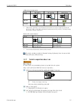
Page 24: ...es with increased luminosity Device search device identification flash fre quency 2 yellow ye 2 Switch status switch output 2 lit If the sensor is covered by medium 3 red rd Warning Maintenance required flashing Error remediable e g invalid calibration Fault device failure lit see Diagnostics and troubleshooting 4 yellow ye 1 Switch status switch output 1 lit If the sensor is covered by medium The...

Page 25: ... yellow ye 2 3 yellow ye 1 10 3 Commissioning with an operating menu If an existing configuration is changed measuring operation continues The new or modified entries are only accepted once the setting has been made Parameter changes are not accepted until after the parameters have been downloaded If using block configuration parameter changes are accepted only after the parameters have been downl...

Page 26: ...lication menu level Configuration Parameter Application Active switchpoints User 2 Immerse the device in the medium to be detected 3 Adopt the εr of the process medium present Configuration Parameter Application User Calibration Get Calibration 1 2 The switch limits can be adjusted accordingly 11 2 Advanced settings 11 2 1 Process fluid For reliable point level detection the device can be adapted ...

Page 27: ...or signal free 1 Very coarsely pored foam cannot be detected by the sensor The device is delivered with the Standard setting Optionally it can be ordered with Extended as the default setting 11 3 Switch output function test LWARNING Risk of injury Ensure that no uncontrolled processes are activated in the system Carry out a function test while the device is in operation 1 Hold the test magnet agai...

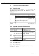
Page 28: ...rrectly attached to the IO Link master Check wiring and cables No transmission of process data There is an error in the device Correct errors that are dis played as a diagnostic event 12 2 Diagnostic information via LED indicator LED indicator on housing cover Malfunction Possible cause Corrective action Green LED not lit No power supply Check plug cable and power supply Red LED flashing Overload ...

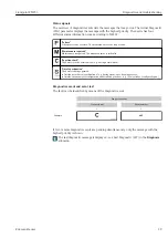
Page 29: ...id A0013959 Function check The device is in the service mode e g during a simulation A0013958 Out of specification The device is being operated Outside its technical specifications e g during warm up or cleaning process Outside the parameter configuration undertaken by the user e g level outside of configured span Diagnostics event and event text The fault can be identified by means of the diagnos...

Page 30: ... check passed Sensor check Information IO Link Information 0x1815 Timeout Reedcontact Timeout reed contact Remove test magnet S825 Warning IO Link Warning 0x1812 Ambient temperature outside of specifica tion Ambient temperature outside of specification Operate device in the specified temperature range 1 EventCode as per IO Link standard 1 1 12 4 Behavior of the device in the event of a fault The d...

Page 31: ... the behavior of the switch output or current output might be changed Make sure that downstream processes are not started unintentionally The reset is not subject to additional locking such as in the form of device locking The reset also depends on the device status Any customer specific configuration carried out at the factory is not affected by a reset customer specific configuration remains The...

Page 32: ...s to the sensor in the process 14 Repairs Repair is not envisaged for this measuring device 14 1 Return The requirements for safe device return can vary depending on the device type and national legislation 1 Refer to the website for more information http www endress com support return material 2 Return the device if repairs or a factory calibration are required or if the wrong device was ordered ...

Page 33: ...extended order code max 60 alphanumeric characters Factory setting As per order specifications ENP_VERSION Navigation Identification ENP_VERSION Description Displays the ENP version ENP electronic name plate Application Specific Tag Navigation Identification Application Specific Tag Description Used for unique identification of device in the field Enter device tag max 32 alphanumeric characters Fa...

Page 34: ...nk C485 sim ulation active The simulation must be ended actively via the menu If the device is discon nected from the power supply during the simulation and power is then resupplied simulation mode is not resumed and instead the device continues operation in measuring mode Options OFF OU1 HIGH OU1 LOW Simulation Switch Output 2 OU2 Navigation Diagnosis Simulation Switch Output 2 OU2 Description Th...

Page 35: ...OFF ON Factory setting OFF Sensor check Navigation Diagnosis Sensor check Description This parameter is used to test if the measuring point is functioning correctly The sensor must not be covered and must be free of residue The device compares the cur rent measured values with the measured values from the factory calibration The device must be removed before the sensor check since the free value i...

Page 36: ...n one another the parameters are described all together SP1 switch point 1 SP2 switch point 2 rP1 switchback point 1 rP2 switchback point 2 Description The switching sensitivity of the sensor can be configured using the switch point and switchback point The switch sensitivity can be adapted to the medium depending on the DC value dielectric constant or conductivity of medium Sensor switches if the...

Page 37: ...ng back and forth at the switch limits is suppressed Switch on value Last value selected prior to switching off Options No selection The user is free to edit the values Input range 15 to 100 Switching delay time Output 1 2 dS1 dS2 Switchback delay time Output 1 2 dR1 dS2 Navigation Application Output Switch 1 2 Switching delay time Output 1 2 dS1 dS2 Application Output Switch 1 2 Switchback delay ...

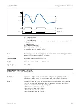
Page 38: ...lly closed contact MAX Coverage of sensor SP1 Switch point 1 SP2 Switch point 2 rP1 Switchback point 1 rP2 Switchback point 2 dS1 Set time for which the specific switch point must be reached continuously without interruption until an electrical signal change takes place dR1 Set time for which the specific switchback point must be reached continuously without interruption until an electrical signal...

Page 39: ...tion Parameter System Unit changeover UNI µC temperature Description This parameter is used to select the electronics temperature unit Once a new electronics temperature unit has been selected the new unit is calculated and displayed Switch on value Last unit selected prior to switching off Options C F K Factory setting C Minimum µC temperature Navigation Parameter System Minimum µC temperature De...

Page 40: ... configuration carried out at the factory is not affected by a reset customer specific configuration remains The following parameters are not reset when a reset is performed Minimum µC temperature Maximum µC temperature Last Diagnostic LST Operating hours Note The last error is not reset in a reset Device Access Locks Data Storage Lock 1 Activation deactivation of DataStorage 1 The Device Access L...

Page 41: ...6 1 1 Test magnet TEST N A0021732 9 Test magnet Order number 71267011 16 1 2 Hexagon tubular socket wrench 32 mm A0038864 10 Hexagon tubular socket wrench Order number 52010156 To mount the device in locations that are difficult to access 16 1 3 Plug in jack ye 1 ye 2 gn 27 5 1 08 40 1 57 11 Dimensions of plug in jack engineering unit mm in Example M12 with LED ...

Page 42: ...m 16 ft PVC cable gray Slotted nut Cu Sn Ni Body PUR blue 52010285 52 5 2 07 ø20 0 8 12 Dimensions of self terminated connection engineering unit mm in Plug in jack M12 IP67 without LED Straight self terminated connection to M12 plug Slotted nut Cu Sn Ni Body PBT 52006263 Core colors for M12 plug 1 BN brown 2 WT white 3 BU blue 4 BK black 16 1 4 Process adapter M24 thread Material For all versions...

Page 43: ...ssel ø 29 mm 1 14 in Installation in pipe G 1 Available versions ø 53 mm 2 09 in Installation on vessel ø 60 mm 2 36 in Installation on pipe M24 Available versions ø 65 mm 2 56 in Installation on vessel 16 1 6 Grooved union nut DIN11851 A0023556 14 Sample drawing of grooved union nut Material For all versions 304 1 4307 For milk pipe DIN11851 Available versions DN25 F26 DN40 F40 DN50 F50 ...

Page 44: ...ns if the point level is reached or if faults or a power outage occur Maximum point level detection MAX e g for overfill protection Minimum point level detection MIN e g to protect pumps from dry running Residual voltage 3 V Residual current 100 µA 17 3 Performance characteristics Reference operating conditions The following reference conditions apply to the performance characteristics Ambient tem...

Page 45: ... cleaning agents from the outside in accordance with Ecolab test Electromagnetic compatibility Electromagnetic compatibility in accordance with all the relevant requirements of the EN 61326 series For details refer to the Declaration of Conformity Only the requirements of IEC EN 61131 9 are met if IO Link communication is used If the device is installed in plastic structures its function may be in...

Page 46: ...industries refer to the Endress Hauser DC manual CP01076F the Endress Hauser DC Values App available for Android and iOS Adhesive and viscous media Setting Light buildup Heavy buildup Surface drying Standard Extended 1 1 1 Surface drying or insulating non homogeneous layers can cause the sensor to signal free and should therefore be avoided or eliminated particularly in maximum safety mode overflo...

Page 47: ...perature 39 Media 7 Menu Overview 20 Parameter description 33 Minimum µC temperature 39 N Nameplate 11 O Operating hours 39 Operating menu Overview 20 Parameter description 33 Operational safety 8 Output 1 2 OU1 OU2 38 P Parameter 36 Product safety 8 R Registered trademarks 6 Requirements for personnel 7 Reset to factory settings RES 30 40 Return 32 S Safety instructions Basic 7 Safety Instruction...

Page 48: ...www addresses endress com 71423738 71423738 ...

Reviews: