background image

Liquipoint FTW23 IO-Link

Commissioning

Hauser

19

rP1

SP1

OU1

rP2

SP2

A

OU2

%

HNO (MIN)

HNC (MAX)

t

1
0

1
0

{

  A0034529

 3

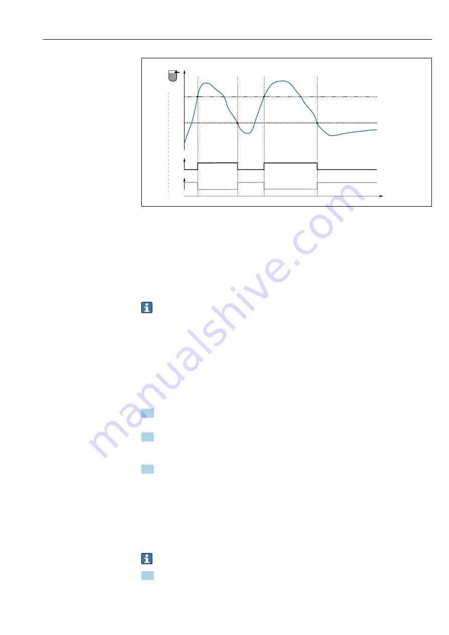
Calibration (default)

0

0-signal, output open

1

1-signal, output closed

A

Hysteresis (difference between the value of the switch point "SP1" and the value of the switchback point "rP1")

%

Coverage of sensor

HNO Normally open contact (MIN)
HNC Normally closed contact (MAX)
SP1 Switch point 1 / SP2: Switch point 2
rP1 Switchback point 1 / rP2: Switchback point 2

Recommended assignment of switch outputs:

• MAX mode for overfill protection (HNC)

• MIN mode for dry running protection (HNO)

9.4  

Window function, media detection/differentiation

Unlike the hysteresis, media are detected only if they are within the defined window.

Depending on the medium, a switch output can be used here.

9.4.1  

Wet calibration

1. Navigate to the Application menu level

 Setting: 

Active switchpoints

 = 

User

2. Configure the behavior of the switch output.

 Setting: 

Output 1/2 (OU1/2)

 = 

Window normally open (FNO)

 or 

Window

normally closed (FNC)

3. Immerse the device in the medium to be detected.

 Setting: 

Calibrate coverage, Output 1/2 (OU1/2)

Setting: 

Switch point value (Coverage), Output 1/2 (FH1/2)

 and 

Switchback

point value (Coverage), Output 1/2 (FL1/2)

The automatically generated switch limits can be adjusted accordingly.

9.4.2  

Dry calibration

This calibration is suitable if the measured values of the medium are known.

For reliable detection of the medium, the process window must be sufficiently large.

1. Navigate to the Application menu level

 Setting: 

Active switchpoints

 = 

User

Summary of Contents for IO-Link Liquipoint FTW23

Page 1: ...Products Solutions Services Operating Instructions Liquipoint FTW23 IO Link Capacitance point level measurement BA01792F 00 EN 01 17 71378479...

Page 2: ...Liquipoint FTW23 IO Link 2 Endress Hauser Order code Ext ord cd Ser no www endress com deviceviewer Endress Hauser Operations App XXXXXXXXXXXX XXXXX XXXXXX XXX XXXX XX Serial number 1 3 2 A0023555...

Page 3: ...14 8 System integration 15 8 1 Process data 15 8 2 Reading out and writing device data ISDU Indexed Service Data Unit 15 8 3 Overview of diagnostic events 17 9 Commissioning 17 9 1 Function check 18 9...

Page 4: ...esult in serious or fatal injury CAUTION CAUTION This symbol alerts you to a dangerous situation Failure to avoid this situation can result in minor or medium injury NOTICE NOTE This symbol contains i...

Page 5: ...er website www endress com download Documentation Purpose and content of the document Technical Information TI01202F 00 EN This document contains all the technical data for the device and provides an...

Page 6: ...ains in perfect condition during the operating time Measuring devices must be used only for media to which the process wetted materials have an adequate level of resistance The relevant limit values m...

Page 7: ...cohol or oil based liquids and powdered products to be used preferably in pipes and in storage mixing and process vessels with or without an agitator 3 1 Product design 1 3 4 5 6 2 A0024689 1 Product...

Page 8: ...er specifications on the delivery note If one of these conditions is not satisfied contact your Sales Center 4 2 Product identification The following options are available for identification of the me...

Page 9: ...nd ambient temperature Process pressure Certificate symbols communication optional Degree of protection e g IP NEMA Measuring point identification optional Date of manufacture year month Data matrix c...

Page 10: ...es 1 Overfill protection or upper level detection MAX 2 Pump dry running protection MIN 3 Lower level detection MIN Installation in horizontal pipes G 3 4 316L G 3 4 316 L G 3 4316 L G 3 4 316L A00210...

Page 11: ...ad G C Thread M24x1 5 Take account of metallic or non metallic vessels or pipes in accordance with EMC guidelines see Technical Information TI01202F 5 3 Post installation check Is the device undamaged...

Page 12: ...urrent principle IO Link communication on Q1 switch mode on Q2 SIO mode if there is no communication the device switches to the SIO mode standard IO mode The factory set functions for the MAX and MIN...

Page 13: ...ts are de energized see following table Connection for function monitoring using XOR operation Yellow LED ye Red LED rd 0 5A L L 2 1 3 4 K1 K2 Sensor covered 1 2 1 4 Sensor uncovered 4 1 1 2 Fault 2 1...

Page 14: ...uring device while in operation Physical layer the measuring devices supports the following features IO Link specification version 1 1 IO Link Smart Sensor Profile 2nd Edition SIO mode yes Speed COM2...

Page 15: ...emaining 14 bits contain the coverage value 0 to 16384 following conversion using the calculation factor The raw value R must be converted to the coverage value C Coverage by the target system C 200 R...

Page 16: ...r w 73 0 0 0 1 Yes 0 200 Switching delay time Output 1 dS1 81 0x0051 2 UInt16 r w 0 5 s 0 0 1 Yes 0 3 to 600 Switchback delay time Output 1 dR1 82 0x0052 2 UInt16 r w 1 0 s 0 0 1 Yes 0 3 to 600 Output...

Page 17: ...max 64 String ro Capacitance point level switch VendorName 16 0x0010 max 64 String ro Endress Hauser VendorText 17 0x0011 max 64 String ro People for Process Automation Hardware Revision 22 0x0016 ma...

Page 18: ...he value is accepted Incorrect switching is suppressed by adjusting the settings in the switch switchback delay Switch point value Switchback point value parameters 9 3 Hysteresis function level detec...

Page 19: ...are detected only if they are within the defined window Depending on the medium a switch output can be used here 9 4 1 Wet calibration 1 Navigate to the Application menu level Setting Active switchpoi...

Page 20: ...example of wet calibration in the process 1 Navigate to the Application menu level Setting Active switchpoints User 2 Assign switch function to the switch outputs Switch output active if medium detect...

Page 21: ...ion Fault device failure lit error not remediable e g Electronics error Diagnostics and troubleshooting 23 On the metal housing cover IP69 1 there is no external signaling via LEDs A connecting cable...

Page 22: ...ce is in operation Hold the test magnet against the marking on the housing for at least 2 seconds This inverts the current switch status and the yellow LED changes state When the magnet is removed the...

Page 23: ...ble incorrectly attached to the IO Link master Check wiring and cables No transmission of process data There is an error in the device Correct errors that are displayed as a diagnostic event 25 10 2 D...

Page 24: ...aintenance required Maintenance is required The measured value remains valid A0013959 Function check The device is in the service mode e g during a simulation A0013958 Out of specification The device...

Page 25: ...ove text magnet S825 Warning 0x1812 Ambient temperature outside of specification Ambient temperature outside of specification Operate device in the specified temperature range 1 EventCode as per IO Li...

Page 26: ...device 12 1 Return The measuring device must be returned if the wrong device has been ordered or delivered As an ISO certified company and also due to legal regulations Endress Hauser is obliged to fo...

Page 27: ...ints 31 Calibrate coverage Output 1 31 Switch point value Coverage Output 1 32 Switchback point value Coverage Output 1 32 Switching delay time Output 1 33 Switchback delay time Output 1 33 Output 1 3...

Page 28: ...he extended order code max 60 alphanumeric characters Factory setting As per order specifications ENP_VERSION Navigation Identification ENP_VERSION Description Displays the ENP version ENP electronic...

Page 29: ...C485 simulation active The simulation must be ended actively via the menu If the device is disconnected from the power supply during the simulation and power is then resupplied the simulation mode is...

Page 30: ...cover IP69 there is no external signaling via LEDs 21 Options Off On Factory setting Off Sensor check Navigation Diagnostics Sensor check Description This parameter is used to test if the measuring po...

Page 31: ...Application Reset user switchpoints Note This parameter is visible only if the User option is selected in the Active Switchpoint parameter Description After selecting an output switch point OU1 or OU...

Page 32: ...ivity of medium Sensor switches if there is slight coverage very sensitive Sensor switches if there is heavy buildup not sensitive The set value for the switch point SP1 SP2 must be greater than the s...

Page 33: ...Medium 2 process window 2 FNO Closing FNC NC contact 1 FH1 FH2 Upper value process window FL1 FL2 Lower value process window Note The various points for the switching delay can be adjusted to ensure...

Page 34: ...ge during the delay time the delay time starts again from scratch rP1 SP1 OU1 HNO MIN A 1 0 dS1 dR1 dS1 rP2 SP2 OU2 HNC MAX t 1 0 A0034590 0 0 signal output open in the quiescent state 1 1 signal outp...

Page 35: ...1 HNO Output 2 OU2 HNC 14 3 2 System Operating hours Navigation System Operating hours Description This parameter counts the operating hours in minutes during the period in which operating voltage is...

Page 36: ...igation System Reset to factory settings RES Description LWARNING Confirming the Standard Command with Reset to factory settings causes an immediate reset to the factory settings of the order configur...

Page 37: ...nch hex bolt 32 AF 52010156 Process adapter M24x1 5 weld in adapter slotted nut and seals see TI00426F 00 EN Description Order number Cable plug in jack Engineering unit mm in M12 IP69 with LED elbowe...

Page 38: ...LST 29 M Maximum C Temperature 36 Menu Description of device parameters 28 Overview 27 Minimum C Temperature 36 N Nameplate 9 O Operating hours 35 Operating menu Description of device parameters 28 Ov...

Page 39: ......

Page 40: ...www addresses endress com 71378479 71378479...

Reviews: