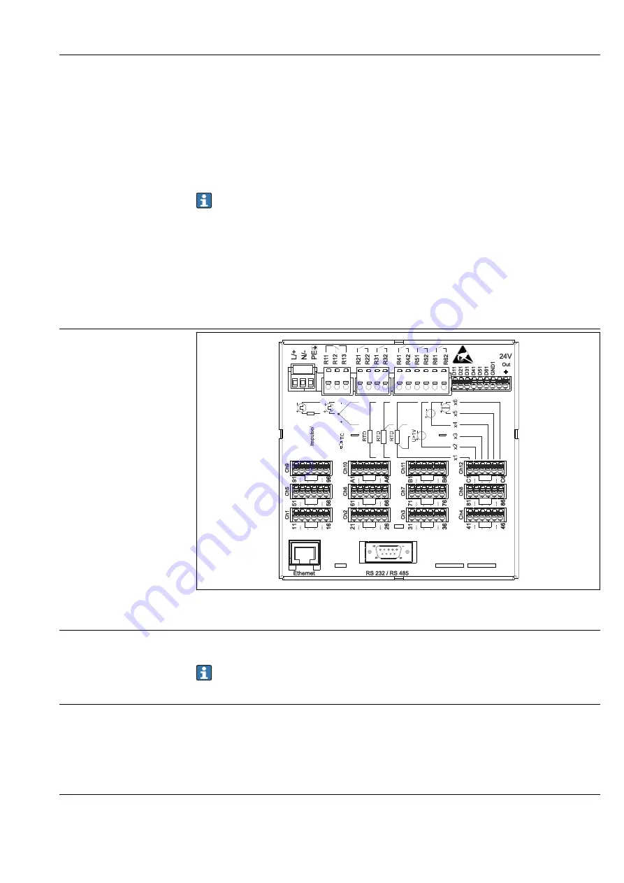
Ecograph T, RSG35
Technical data
Hauser
69
at the device). Appropriate internal device wiring measures must be taken to allow
unrestricted operation when EMC interference is present. These measures have been
taken into account for this device. Operation in the event of disturbance variables as per
NAMUR NE21 is thus guaranteed.
Where applicable, national installation regulations and guidelines must be observed
during the installation! Where there are large differences in potential between the
individual grounding points, only one point of the shielding is connected directly with the
reference ground.
If the shielding of the cable is grounded at more than one point in systems without
potential matching, mains frequency equalizing currents can occur. These can damage
the signal cable or significantly impact signal transmission. In such cases the shielding
of the signal cable is to be grounded on one side only, i.e. it may not be connected to
the ground terminal of the housing. The shield that is not connected should be
insulated!
15.4 Power supply
Terminal assignment
5
6
9
1
Frequency
A0019304
12
Terminals on back of device
Supply voltage
• Extra-low voltage power supply unit ±24 V AC/DC (-10% / +15%) 50/60Hz
• Low voltage power supply unit 100 to 230 V AC (±10%) 50/60Hz
An overload protection element (rated current ≤ 10 A) is required for the power cable.
Power consumption
• 100 to 230 V: max. 35 VA
• 24 V: max. 24 VA
The power actually consumed depends on the individual operating state and the device
version (LPS, USB, brightness of screen, number of channels, etc). The active power here is
approx. 3 W to 20 W.
Power supply failure
Battery-backed time and data memory. The device starts automatically following a power
failure.


