background image

Products

Solutions

Services

EA00009C/07/A2/03.15

71293466

Einbauanleitung / 

Installation Instructions

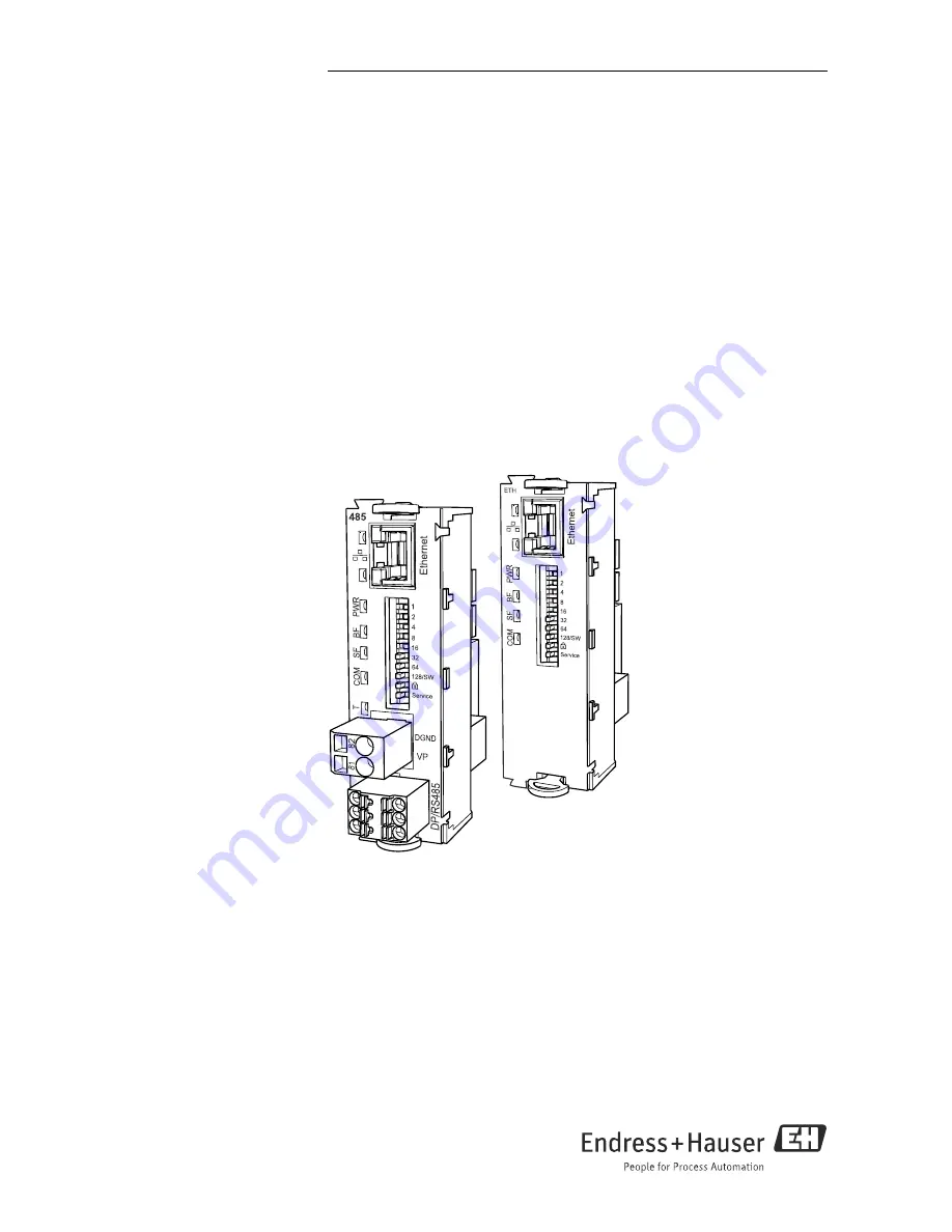
Kit CM44x / CSXxx / CA80XX

Modul 485 oder ETH / Module 485 or ETH

Für Ethernet-Konfiguration, PROFIBUS, Modbus

For Ethernet configuration, PROFIBUS, Modbus

Summary of Contents for 485

Page 1: ...vices EA00009C 07 A2 03 15 71293466 Einbauanleitung Installation Instructions Kit CM44x CSXxx CA80XX Modul 485 oder ETH Module 485 or ETH Für Ethernet Konfiguration PROFIBUS Modbus For Ethernet configuration PROFIBUS Modbus ...

Page 2: ...mm 1 Modul Blindabdeckung 12 mm 1 Typenschild CM44 inside 1 Typenschild Upgrade Service 1 Einbauanleitung EA00009C 07 A2 1 2 Werkzeugliste 1 3 Zusätzliche Dokumentation Betriebsanleitung Liquiline CM44x BA00444C 07 DE Betriebsanleitung Liquiline CM44xR BA01225C 07 DE Betriebsanleitung Liquistation CSF48 BA00443C 07 DE Betriebsanleitung Liquiline System CA80XX z B BA01240C 07 DE a0015916 ...

Page 3: ...egenstände z B Messer zum Öffnen des Gehäu ses Verwenden Sie ausschließlich einen geeigneten Kreuzschlitz Schraubendreher Lösen Sie die Gehäuseschrauben schrittweise Beginnen Sie mit einer beliebigen Schraube und lösen Sie danach die diagonal gegenüber liegende usw Beim Schließen des Gehäuses gehen Sie ebenfalls schrittweise und in diagonaler Folge vor a0012688 Abb 1 GehäuseschraubenmitKreuzschlit...

Page 4: ...geöffnet werden 2 1 3 CA80XX Das Controller Gehäuse verfügt über einen separaten Anschlussraum Nach Lösen der sechs Deckelschrauben kann dieser geöffnet werden a0012843 Abb 3 6 Deckelschrauben mit Kreuzschlitz Schraubendreher lösen um Dis play deckel zu öffnen a0013238 Abb 4 Displaydeckel geöffnet Ausführung mit Basismodul L 1 Basismodul L 2 Probenehmersteuerung ...

Page 5: ...hr Gerät bietet Benutzen Sie z B den Konfigurator auf der jeweiligen Produktseite z B www products endress com cm442 oder cm444R CSF48 oder Hinweise Sie können immer nur einen Feldbus verwenden Beispiel Sie hatten bisher HART aktiv Nach Einbau des Moduls 485 aktivieren Sie PROFIBUS DP über Freischaltcode Anschließend ist HART deaktiviert Bei CM442 442R werden mit dem Einbau des Moduls 485 evtl bis...

Page 6: ...fügbaren Steckplätze belegt Bei allen anderen Geräten haben Sie weitere Steckplätze für andere Elektronikmodule zur Verfügung Wenn in Ihrem Gerät bereits ein anderes Modul an Steckplatz 2 eingebaut ist 1 Entfernen Sie das Modul Benutzen Sie zum Herausziehen die Ziehhilfen Falls in Ihrem Gerät nur das Basismodul vorhanden ist 2 Entfernen Sie die Modulendabdeckung 3 Setzen Sie das Feldbusmodul in di...

Page 7: ...ontage Endress Hauser 7 5 Setzen Sie zuletzt die Modulendabdeckung wieder ein Im Bild ist das Feldbusmodul das letzte Wenn Sie noch weitere Module verwenden set zen Sie die Endabdeckung nach dem letzten Modul ein ...

Page 8: ... Spannung anliegt WARNUNG Fehlende Modulabdeckung Berührungsschutz ist nicht gegeben Gefahr von Stromschlägen Wenn Sie ihre Hardware ändern oder erweitern Füllen Sie die Steckplätze immer von links nach rechts CM44x oder von oben nach unten CSFXXxx auf Lassen Sie keine Lücke Wenn nicht alle Steckplätze belegt sind Stecken Sie nach dem CM44x oder unterhalb des CSFXXxx letzten Moduls immer eine Blin...

Page 9: ...egramm wird empfangen oder versendet T Bus termination YE Nur 485 bei ETH nicht vorhanden Aus Keine Terminierung Ein Terminierung wird verwendet DIP Schalter auf der Modulfront DIP Werkseinstell Belegung 1 128 ON Busadresse Inbetriebnahme Kommunikation OFF Schreibschutz ON Konfiguration ist über den Bus nicht möglich nur über Vor Ort Bedienung Service OFF Bei Schalterstellung ON werden die Benutze...

Page 10: ...e Datenübertragungs rate 12 MBit s PROFIBUS DP Modbus RS485 nur Modul 485 M12 Y Stück Verdrahtung im Y Stück Pin Belegung in Stecker und Buchse a0016310 Abb 6 M12 Steckverbindung a0016311 Abb 7 Verdrahtung a0016312 Abb 8 Stecker links und Buchse rechts 1 P5V 5 V Versorgung für externen Abschlusswiderstand 2 A GN Signal RxD TxD N 3 P0V Referenzpotenzial für P5V 4 B RD Signal RxD TxD P 5 n c nicht v...

Page 11: ...scher Anschluss Endress Hauser 11 Ethernet Webserver Interner Anschluss Pin Belegung in Stecker und Buchse a0016313 Abb 9 Ethernetbuchse a0016314 Abb 10 Stecker links und Buchse rechts 1 Tx 2 Rx 3 Tx 4 Rx Schirm Gewinde ...

Page 12: ...Stellung ON Der interne Terminierungswiderstand wird verwendet a0016306 Abb 12 Aufbau des internen Terminierungswiderstands 2 Externer Terminierungswiderstand Lassen Sie in diesem Fall die DIP Schalter auf der Modulplatine in der Position OFF Werksein stellung Schließen Sie den Widerstand zu seiner 5 V Versorgung an die Klemmen 81 und 82 auf der Vorderseite des Moduls 485 an Der externe Terminieru...

Page 13: ... 1 Blanking cover for modules 12 mm 1 Nameplate CM44 inside 1 Nameplate upgrade service 1 Installation Instructions EA00009C 07 A2 4 2 Tool list 4 3 Documentation Operating Instructions Liquiline CM44x BA00444C 07 EN Operating Instructions Liquiline CM44xR BA01225C 07 EN Operating Instructions Liquistation CSF48 BA00443C 07 EN Operating Instructions Liquiline System CA80XX e g BA01240C 07 EN a0015...

Page 14: ...ny sharp or pointed objects such as a knife to open the housing Only use a suitable Phillips screwdriver Release the housing screws step by step Start with any screw and then release the screw diagonally opposite etc When closing the housing also tighten the screws step by step in a diagonally opposite sequence a0012688 Fig 13 Releasing housing screws in a diagonally opposite sequence with Phillip...

Page 15: ... the connection compartment 5 1 3 CA80XX The controller housing has a separate connection compartment Release the 6 housing screws to open the connection compartment a0012843 Fig 15 Release 6 housing screws with a Phillips screwdriver to open the display cover a0013238 Fig 16 Controller with L basic module opened 1 L basic module 2 Sampler controller ...

Page 16: ...se the configurator on the product s web site www products endress com cm442 or cm444R or CSF48 Notes You can use a single fieldbus protocol only Example HART is activated on your device After the installation of the 485 module you enter an activation code for PROFIBUS DP The HART communication will now be deactivated When installing the module to a CM442 442R all possibly existing current outputs...

Page 17: ... CM44x field housing only You must install the 485 or ETH module into slot 2 With a CM442 442R device all possible slots will be used then With all other devices you will have more slots available for the installation of extension modules If there is already another module in slot 2 of your device 1 Remove it Use the clips to pull out the module If there is only the basic module 2 Remove the modul...

Page 18: ...nal 6 mm blind cover behind the module The blind cover is in the kit s scope of delivery 5 Insert the module end cover The graphic shows the fieldbus module as last in the sequence If you have more modules insert the end cover behind the module last in sequence ...

Page 19: ...ginning any wiring work make sure voltage is not applied to any of the cables WARNING Module not covered No shock protection Danger of electric shock If you are modifying or extending your hardware always fill the slots from left to right Do not leave any gaps If not all the slots are occupied always insert a dummy or end cover into the slot to the right of the last module This ensures the unit is...

Page 20: ...n Connection is active Flashing Data transmission RJ45 10 100 YE Off Transmission rate 10 MBit s On Transmission rate 100 MBit s PWR Power GN Supply voltage is applied and module is initialized BF Bus failure RD Bus failure does not apply for module ETH SF System failure RD System failure COM Communication YE Modbus message sent or received T Bus termination YE For module 485 only not available wi...

Page 21: ...ON the user settings for Ethernet addressing are saved and connection settings programmed at the factory are activated IP address 192 168 1 212 subnet mask 255 255 255 0 gateway 0 0 0 0 DHCP off When the switch is set to OFF the saved user settings are active again PROFIBUS DP Modbus RS485 module 485 only M12 Y section Wiring in Y section Pin assignment in connector and socket a0016310 Fig 18 M12 ...

Page 22: ...44x 22 Endress Hauser Ethernet Web server Internal connection Pin assignment in connector and socket a0016313 Fig 21 Ethernet socket a0016314 Fig 22 Connector left and socket right 1 Tx 2 Rx 3 Tx 4 Rx Shield Thread ...

Page 23: ...witches to the ON position The internal terminating resistor is used a0016306 Fig 24 Structure of the internal terminating resistor 2 External terminating resistor Here leave the DIP switches on the module board in the OFF position factory setting Connect the resistor to terminals 81 and 82 on the front of module 485 for 5 V power supply The external terminating resistor is used Fig 23 DIP switche...

Page 24: ...www addresses endress com ...

Reviews: