These assembly diagrams are intended as a guide – if in doubt consult a qualified electrician.
NOTE – The uplight unit YG-862-SS CANNOT be used as a downlight and the downlighter – YG-861-
SS CANNOT be used as an uplight. This is because of the position on the drain holes in the two
construction.
Assembly / user instructions
Endon Lighting
LS9 0SE
20150807
N210 117
Diagram A
Diagram B
Diagram C
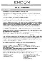
1. Determine the position of your light
fitting taking into account the exit
position of the cable. Ensure that the
mounting surface is solid, preferably
a brick or block wall and ensure that
there are no other cables or pipes
beneath the surface. Use
appropriate fixings. Wall plugs and
screws as supplied are shown here.
2.
Diagram A
.
Separate the plastic
back plate from the fitting by
removing the two domed nuts /
washers (1) on the front of the
fitting. Leave the threaded (2) bolts
in the back plate.
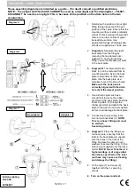
3. Diagram B
. The internal terminal
block (3) can be removed from its
mounting position inside the back
plate to ease fitment of the back
plate. Use the back plate as a
template to mark the screw holes.
Make sure the back plate is
correctly aligned with the drain
hole (4) at the lowest position.
4.
Use a sharp object such as a
screwdriver to pierce the rubber
grommet in the back plate. Feed the
incoming cable (5) through the
rubber grommet and attach the back
plate to the wall. Do not over tighten
as this could damage the back plate.
5.
Connect the house wiring to the
internal terminal block (3).
NOTE:
This is a Class I fitting and
must
be earthed.
See wiring details.
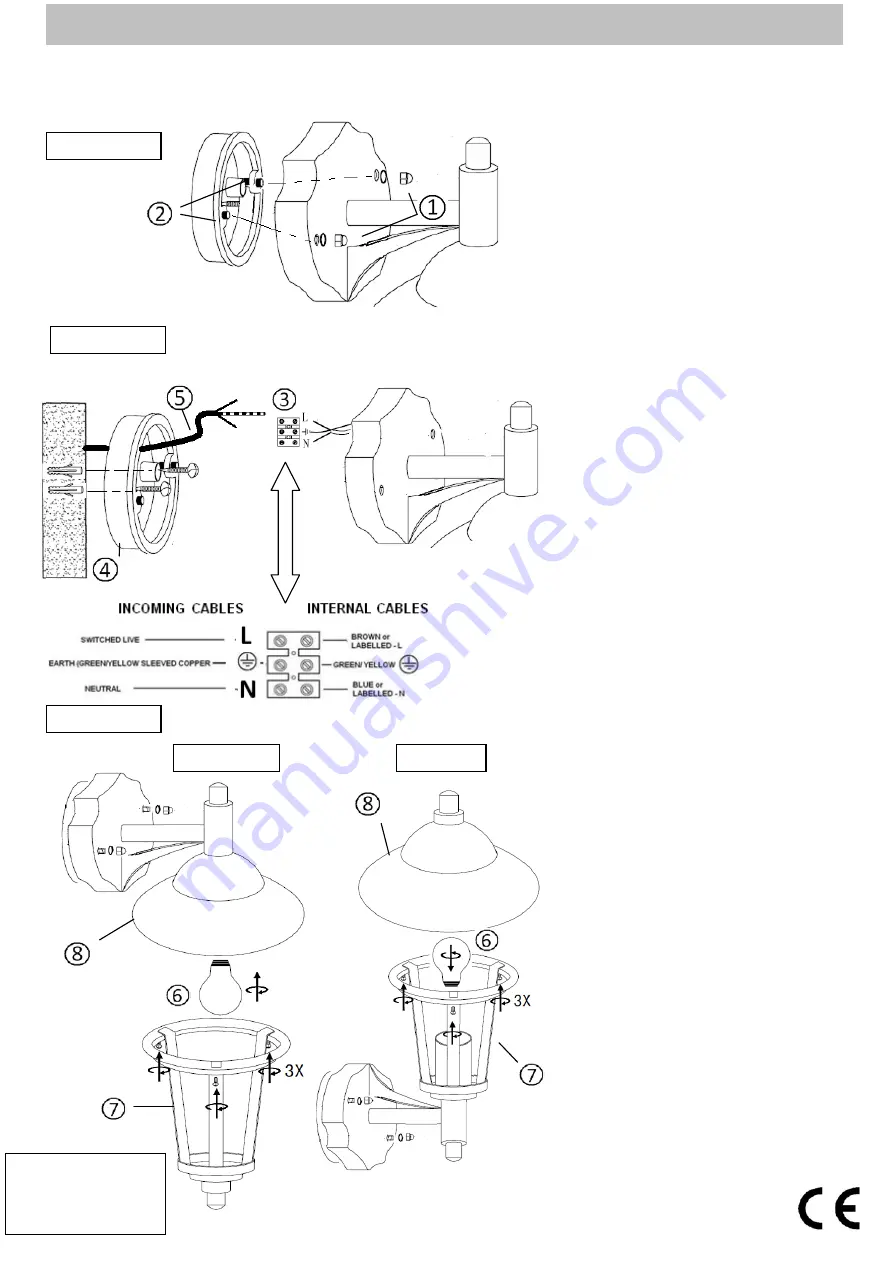
6. Diagram C.
Place the fitting over
the back plate, ensuring that the
bolts in the back plate are aligned
with the holes in the front of the
fitting. Replace the domed nuts /
washers to secure the fitting. Fit the
bulb (6) (not supplied) into the lamp
holder.
NOTE:
Never fit bulbs of a
higher wattage or of a type other
than those specified on the label
(as these may cause overheating
and damage the fitting).
7.
Fit the cage (7) and cover (8)
together with the 3 x securing
screws.
8. Turn on the power and test.
Uplighter
Downlighter


