
Endon Lighting
LS9 0SE
20150807
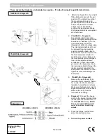
These assembly diagrams are intended as a guide – if in doubt consult a qualified electrician.
Assembly / user instructions
N210 108
YG-4000-SS - Diagram A
YG-4001-SS- Diagram B
1. Determine the position of your light
fitting taking into account the exit
position of the cable. Ensure that
the mounting surface is solid,
preferably a brick or block wall and
ensure that there are no other
cables or pipes beneath the
surface. Use appropriate fixings.
Wall plugs and screws as supplied
are shown here.
2.
YG-4000-SS – Diagram A
.
Separate the plastic back plate
from the fitting by removing the two
domed nuts / washers (1) on the
front of the fitting. Leave the
threaded (2) bolts in the back plate.
The internal terminal block (3) can
be removed from its mounting
position inside the back plate to
ease fitment of the back plate. Use
the back plate as a template to
mark the screw holes. Make sure
the back plate is correctly aligned.
Use a sharp object such as a
screwdriver to pierce the rubber
grommet in the back plate. Feed
the incoming cable (4) through the
rubber grommet and attach the
back plate to the wall. Do not over
tighten as this could damage the
back plate.
3.
YG-4001-SS – Diagram B
.
Remove the wall bracket (5) by
removing the 2 screws (6). Retain
for re-use. Use the bracket as a
template to mark the screw holes.
Make sure the bracket is correctly
aligned and secure to the surface.
Remove the lid (7) from the
terminal block housing.
4.
Diagram C
. Connect the house
wiring to the internal terminal block
(and replace the terminal cover in
the
YG-4001-SS
model).
NOTE:
These are Class I fittings and
must be earthed. See wiring
details.
5.
Place the fittings over the back
plate / bracket and secure.
6.
Turn on the power and test.
Diagram C