


ENDEVCO MODEL 4990A RACK
INSTRUCTION MANUAL
19
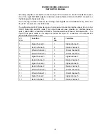
6.
OPERATION
6.1
Connecting Sensors to OASIS 2000
6.1.1
Model 428 Two Channel PE/ISOTTRON Amplifier
Both channel 1 and channel 2 input connectors are BNC. If the cable termination is 10-32
Microdot, use the BNC to 10-32 Microdot adapter supplied with the Model 428 to make the
connection.
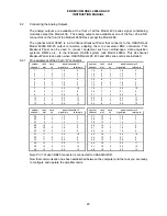
The analog output signals are available at the two BNC output connectors, and also at one of the
four 25-pin “D” connectors on the 4990A rack. Which connector depends on which slot the 428
board resides in. See paragraph 6.2.1 for pin assignments.
6.1.2
Model 433 Three Channel PE/ISOTRON Amplifier
All three input connectors are BNC. If the cable termination is 10-32 Microdot, use the BNC to
10-32 Microdot adapter supplied with the Model 433 to make the connection.
The analog output signals are available at the three BNC output connectors, and also at one of
the four 25-pin “D” connectors on the 4990A rack. Which connector depends on which slot the
433 board resides in. See paragraph 6.2.1 for pin assignments.
6.1.3
Model 436 Three Channel DC Amplifier
The Model 436 should warm up for one hour prior to taking data.
All three input connectors are 9 pin “D”. The input pin assignments are as follows:
•
Pin 4:
S- Sensor Signal Input (White wire of Endevco bridge)
•
Pin 5:
S+ Sensor Signal Input (Green wire of Endevco bridge)
•
Pin 7:
P+ Excitation Voltage (Red wire of Endevco bridge)
•
Pin 8:
P- Excitation Voltage (Black wire of Endevco bridge)
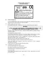
CAUTION: If remote sensing is NOT used, pin 7 and pin 1 must be shorted together and pin 8
and pin 6 must be shorted together to avoid damage to the sensor.
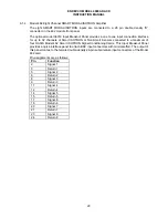
The analog output signals are available at one of the four 25-pin “D” connectors on the 4990A
rack. Which connector depends on which slot the 436 board resides in. See paragraph 6.2.1 for
pin assignments.