background image

ENDEVCO

    www.endevco.com    Tel: +1 (866) ENDEVCO  [+1 (866) 363-3826]

IM 2680/5   083119      

24

07 

MAINTENANCE AND CALIBRATION

The airborne amplifiers are sealed and potted thus there are no user 

serviceable parts.  Cleaning the connectors is important to maintain noise-

free operation.  Annual calibration using sources traceable to the National 

Institute of Standards and Technology (USA) or other recognized standards 

organizations is recommended.
Below is a list of checks to perform prior to returning the unit or contacting 

an applications engineer:

• 

Check the connector wiring making sure that pin A is at the proper 

polarity.  Look for possible shorted pin connections.

• 

Check for damaged cables on the input and output.

• 

Using a DMM, measure the DC bias between pins C&D.  This should 

read approximately 4.65 volts DC. 

• 

Measure input current from the power supply.  See table 5 for the 

current values.

7.1

 Returning the unit

Prior to returning the unit to the factory, contact the applications 

engineering department.  Let the applications engineer know the results 

of any of the above tests.  If it is necessary to return the unit to the factory, 

follow the below procedure:
USA: Contact the customer service department, at the factory, and 

obtain an RMA number.  Include the RMA number on the enclosed 

documentation and the outside of the shipping box.  Include a description 

of the problem encountered and the unit serial number and your contact 

information.
Outside USA: Contact your local representative or distributor and follow 

their instructions. 

Summary of Contents for 2680M1

Page 1: ...rs IEPE accelerometers Variable capacitance accelerometers Piezoresistive pressure sensors Piezoelectric pressure sensors High intensity microphones Inertial sensors Signal conditioners and supportive instrumentation Cable assemblies IM 2680 5 083119 1 Models 2680M1 2685M1 Airborne Amplifier Instruction Manual TBD ...

Page 2: ...access screw 10 4 5 2 Sealing the access screw 10 4 6 How to calculate gain and output level 11 4 7 2685 considerations 12 4 8 What to look for 13 5 0 Environmental considerations 15 5 1 EMC capability 15 5 2 Temperature Effects 15 5 3 High temperature accelerometers 15 6 0 Performance testing 16 6 1 Preferred method 2680 and 2685 16 6 1 1 Hand held shaker method 16 6 1 2 Accelerometer simulator m...

Page 3: ...M7 10 to 100 500 2 0 1 1 Low pass filters An optional low pass filter is factory installed in the airborne amplifier if specified on the Purchase Order Available filters are 2 pole Butterworth filters that provide the unit with a specific frequency response If an airborne amplifier contains an optional filter the model number will contain a three digit suffix dash number to indicate the filter s 5...

Page 4: ...z 80 kHz 402 3 Hz 5 Hz 4 kHz 8 kHz 16 kHz 250 3 Hz 5 Hz 25 Hz 50 Hz 100 Hz 10 kHz for M7 10 kHz for M7 Lower Cutoff Upper Cutoff None 0 7 Hz 3 Hz 2Hz 20 kHz 101 0 7 Hz 3 Hz 2Hz 100 Hz 200 Hz 400 Hz 201 0 7 Hz 3 Hz 2Hz 200 Hz 400 Hz 800 Hz 501 0 7 Hz 3 Hz 2Hz 500 Hz 1 kHz 2 kHz 102 0 7 Hz 3 Hz 2Hz 1 kHz 2 kHz 4 kHz 202 0 7 Hz 3 Hz 2Hz 2 kHz 4 kHz 8 kHz 502 0 7 Hz 3 Hz 2Hz 5 kHz 10 kHz 20 kHz 103 0 ...

Page 5: ...zoelectric accelerometers and microphones The 2685 provides a constant current source and amplifier for an IEPE ISOTRON type accelerometer An IEPE accelerometer has a built in amplifier that requires a constant current power source The transducer provides a low impedance voltage output while maintaining a two wire connection Both the power and the signal output are carried over the same cable The ...

Page 6: ...ely to the carrier Inspect the contents of the shipping carton and verify that the applicable accessories listed in Table 4 are included in the shipment with each airborne amplifier Should it be necessary to return the amplifier to the factory follow the instructions in section 7 1 of this manual It is recommended that an applications engineer be contacted prior to returning the unit since many pr...

Page 7: ...stallation This section covers the connections between the transducer and the airborne amplifiers 04 1 1 2680 input cable The 2680 airborne amplifier is configured to operate with charge mode transducers thus the input cable must be low noise treated Cable assemblies such as the Endevco 3090C or the premium 3090DV are recommended The connector on the airborne amplifier is a 10 32 type 04 1 1 2 Inp...

Page 8: ...lengths will permit an increase of the maximum frequency 04 2 Output connector 2680 2685 A 5 pin connector is provided for the output signals ground and power The output characteristics and pins are common to both the 2680 and the 2685 The 5 pin connector is a bayonet locking type A mating connector is supplied with the amplifier See figure 1 and 2 for the connector pinout locations 04 3 Powering ...

Page 9: ...ing capacitor blocks the DC bias only allowing only the AC signal to be available at pin B With the addition of the series capacitor and bleed resistor in the output a 0 00 V bias level is established The unbiased output is linear from 0 to 4 65 V p p or 0 to 5 00 V p p depending on the specific airborne amplifier used Refer to Table 1 2 for further output data on specific airborne amplifiers 4 5 ...

Page 10: ...ted gain and the gain access screw temporarily seated in the threaded access hole Users may adjust the gain to a desired gain setting prior to installation of an airborne amplifier See table 1 to determine the applicable gain range 4 5 1 Unsoldering the access screw Should it become necessary to remove the screw from a unit that has been solder sealed follow the instructions as follows Preheat an ...

Page 11: ...k sensitivity in pC g or mV g 1 As Eo Fs Where As Amplifiers charge sensitivity or voltage sensitivity in mV g Eo Amplifiers peak full scale output in mV peak FS Amplifier s desired peak full scale output in g peak The next step is to compute the required gain Aq 2 Aq As Sq Where Sq Sensor s sensitivity in pC g or mV g Make sure that the output signal amplitude is compatible with the readout equip...

Page 12: ...f the compliance and bias voltage levels The specified bias level indicated is measured at room temperature and will change as the operating temperature changes Note that compliance voltage is the supply voltage minus 2 3 Volts due to a voltage drop in the regulator circuit Use the following equations to determine the maximum full scale peak output voltage from the IEPE accelerometer To determine ...

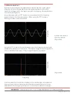
Page 13: ...ing signals close to the full scale output When using the FFT mode a Hanning window is recommended Using the FFT mode on the oscilloscope view the frequency domain and observe the presence of harmonics The below image shows the spectrum of an undistorted sine wave Only a single frequency is present In some cases the time domain display on the oscilloscope can appear as clean as figure 6A but there...

Page 14: ...al frequency on the left and the presence of harmonics in figure 6C Figure 6D is an example of the presence of clipping as seen in the time domain In this case further analysis using the FFT mode is unnecessary since the problem is obvious Figure 6C Figure 6D Amplitude Amplitude Frequency Frequency ...

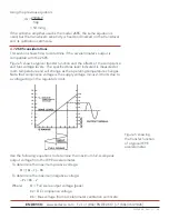
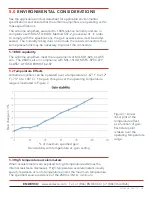
Page 15: ... meet the requirements of MIL STD 826 CLASS Am The 2680 is also in compliance with MIL I 618D MSFC SPEC 279 CLASS1 AF BSD EXHIBIT 62 87 5 2 Temperature Effects Airborne amplifiers can be operated over a temperature of 67 F to 212 F 73 C to 100 C The gain change over the operating temperature range is illustrated in Figure 7 of maximum specified gain Gain stability with temperature vs gain setting ...

Page 16: ...quick test might be conducted prior to installation to verify the unit is operational The most efficient way to test the performance is described in section 6 1 If these instruments are unavailable section 6 2 suggests methods where standard laboratory instrumentation can be used to effectively perform the tests See the appropriate Endevco technical paper for further tests if required 6 1 Preferre...

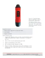
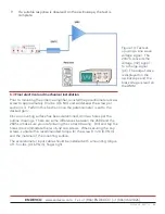
Page 17: ...tes for warm up 2 Install a 10k Ω watt resistor between pins C D 3 Attach an oscilloscope to pins C and D 4 Set the reference shaker frequency to 100Hz 5 Observe a 100 Hz undistorted sine wave on the oscilloscope If the oscilloscope is DC coupled a DC bias of 2 50 volts 3 should also be observed Figure 9 A handheld shaker Endevco REF2520 is ideal for testing system performance The shaker provides ...

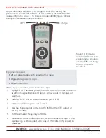
Page 18: ...en using a simulator follow the below steps 1 Apply 28 VDC between pins A and D and confirm that the current is within the specifications in Table 4 Allow about 3 minutes for warm up 2 Install a 10k Ω watt resistor between pins C D 3 Attach an oscilloscope to pins C and D 4 Use the charge output for testing the 2680 or the IEPE output for testing the 2685 5 Set the simulator frequency to 100Hz 6 O...

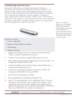
Page 19: ...ltage across the 10k Ω resistor The voltage should read 2 50 VDC 3 4 Connect a charge mode piezoelectric accelerometer to the10 32 input connector using low noise cable 5 Connect an oscilloscope to either or Pins B and D or C D AC coupling is recommended if using pins C D 6 Tap the base of the accelerometer with a wooden pencil or a plastic screwdriver handle 7 Look for an output response on the o...

Page 20: ...pe screen Figure 11 is an example of a response from a hard strike 8 If a response is observed on the oscilloscope the test is complete 9 Install the accelerometer cable in such a way that the DC voltage can be measured This is best accomplished using a pair of 10 32 to BNC cables Endevco 3061 joined by a BNC T connector Amphenol 112461 or equiv per figure 5 10 Refer to the accelerometer s calibra...

Page 21: ...tween pins A and D and confirm that the current is within the specifications in table 4 2 Connect a 10k Ω minimum resistor between pins C and D 3 With a DMM measure the DC voltage across the 10k Ω resistor The voltage should read 2 50 VDC 3 4 Connect the 2947C to the 10 32 connector and the BNC end to a function generator see figure 14 5 Connect an oscilloscope to either or Pins B and D or C D AC ...

Page 22: ...etermined drill two holes per the outline drawings There are some differences between the 2680 and the 2685 so make sure you are following the correct drawing Drill and tap the holes to accommodate the two 6 32 cap screws When securing the cap screws consider the recommended torque for the screw 8 in lb 0 9 Nm and the material of the mounting surface The accelerometer input cable should be install...

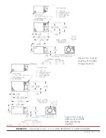
Page 23: ...ENDEVCO www endevco com Tel 1 866 ENDEVCO 1 866 363 3826 IM 2680 5 083119 23 Figure 15A Outline drawing of the 2680 Charge amplifier Figure 15B Outline drawing for the 2685 IEPE ISOTRON amplifier ...

Page 24: ...k for damaged cables on the input and output Using a DMM measure the DC bias between pins C D This should read approximately 4 65 volts DC Measure input current from the power supply See table 5 for the current values 7 1 Returning the unit Prior to returning the unit to the factory contact the applications engineering department Let the applications engineer know the results of any of the above t...

Page 25: ... because of a loose connector 5 When testing in a high humidity environment curl the cable into a drip loop near the transducer and the airborne amplifier Any condensation that occurs will then be drawn away from the connector Apply Dow Corning Silastic 732RTV adhesive sealant to connector threads and outer joints to prevent moisture from entering the connector 6 Keep cable connectors and transduc...

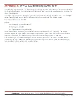
Page 26: ...the voltage signal is thus converted to a charge signal The transfer function is Q EC Where Q Charge in picocoulombs pC E Voltage in volts V C Capacitance in picofarads pF Since the capacitor is 1000 pF the transfer function simplifies to Q pC E mV The charge must be expressed in pC peak if the voltage is expressed in peak units The calibration reference frequency is 100 Hz thus this frequency is ...

Reviews: