


ENDEVCO 2680
INSTRUCTION MANUAL
IM2680
Page 3-3
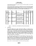
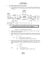
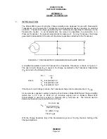
Aq = Charge Amplifier Gain in mV/pC (see paragraph 4.2.)
Cin = Input Capacitance in pF. Includes Accelerometer Capacitance
(Cp) and Cable Capacitance (Cc) between Accel and T-Block
E. Set switch S2 in Figure 3-1 test setup to OSC position. Readout devices should receive
output of Oscillator.
F. Adjust Oscillator for a frequency between 20 and 50 Hz, and for an Output Voltage obtained
for Ein in Step D. Verify Oscillator frequency on Oscilloscope and Output Voltage on DVM.
G. Set switch S2 to OUT position and ensure switch S1 is in CAL position. DVM should
indicate the value of voltage established for Charge Amplifier's Output (Eo) in Step D. This
is accomplished by setting the oscillator's output to Ein, and applying this voltage to the
input of the T-Block.
H. Since both an input (Ein) and output (Eo) has been established and verified, the Voltage
Insertion Test can now be used to verify system integrity anytime the system is suspected of
being faulty, or assurance that the system is performing to specification.
I.
Set switch S1 to OPR (operate) position and S2 to OUT position for normal system
operation.
4.
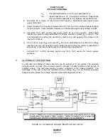
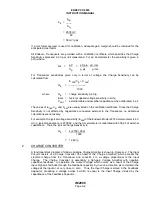
ALTERNATE TEST METHOD
An Alternate Test Method (charge insertion) can be performed to the system. The alternate
method permits no check of the Accelerometer for an open, but does indicate a short by lack of
amplifier output. The test does provide "in-place" calibration of the Charge Amplifier. The
advantage of this test is that the Oscillator Output Voltage (Ein) can be inserted anywhere
between Accelerometer and Charge Amplifier without affecting System Test.
FIGURE 3-2: ALTERNATE CHARGE INSERTION TEST SETUP


