background image

5-16.Measuring AC and DC Signals

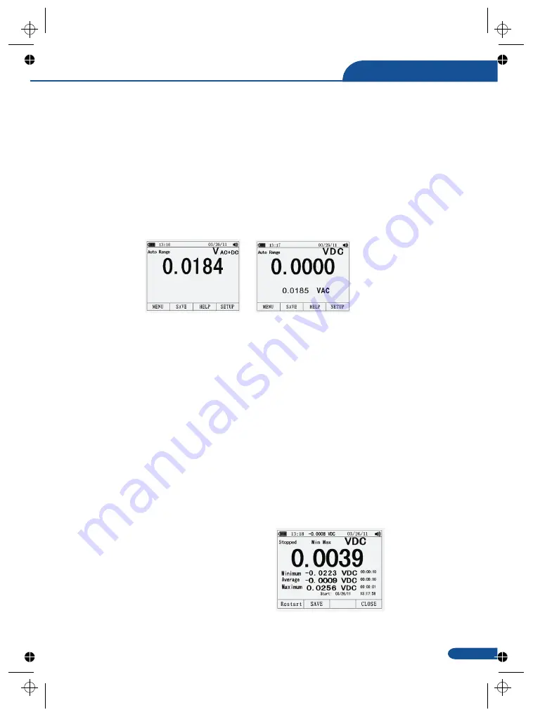
The Meter is capable of displaying both AC and DC signal components (voltage or current)
as two separate readings or one AC+DC(RMS) value combined. As shown in Figure , the
Meter displays ac and dc combinations two ways: DC displayed over AC (DC,AC), and AC
combined with dc (AC+DC). Select one of these three displays using the Function and Mode
menu. With the rotary switch set to V, mV, A, mA,or uA, press the soft key labeled Menu.
Move the menu selector to the menu item labeled AC+DC. At this point, three different soft key
labels indicate AC+DC (F1),and DC,AC (F2). Press the soft key that presents these two
signals as needed. While in any of the three AC+DC modes, peak measurements, frequency,
duty cycle, relative %, and period measurements are not allowed. In addition to these modes,
MIN MAX, relative.

5-17.Capturing Minimum and Maximum Values

The MAX MIN Record mode captures minimum, average, and maximum input values. When the
input goes below the recorded minimum value or above the recorded maximum value, the
Meter beeps and records the new value. The Meter stores the elapsed time since the recording
session was started at the same time. The MAX MIN mode also calculates an average of all
readings taken since the MAX MIN mode was activated. This mode is for capturing intermittent
readings,recording minimum and maximum readings unattended, or recording readings while
equipment operation precludes watching the Meter. The MIN MAX mode is best for recording
power supply surges, inrush currents, and finding intermittent failures. Response time is the
length of time an input must stayat a new value to be captured as a possible new minimumor
maximum value.

To activate the MAX MIN mode, press MAX MIN. As shown in Figure, the Meter displays e
at the top of the measurement page, and the MAX MIN start date and time along the bottom of the
page. In addition, the recorded maximum, average, and minimum values appear in the secondary
display with their respective elapsed times.

To stop a MIN MAX recording session, press

the softkey labeled Stop. The summary
information in the display freezes, and the
softkeys change function to allow saving
the collected data. Pressing the softkey
labeled Close exits the MIN MAX record

session without saving the collected data.

23

True RMS Multimeter

Summary of Contents for ET2704

Page 1: ...aintenance Appendix 2 Specifications True RMS Multimeter Oscilloscope Section 4 Feature 5 6 General Specification 6 6 7 8 11 30 32 37 40 42 51 52 54 55 57 Meterbox User s Guide 1 Meter Operation 2 Met...

Page 2: ...True RMS Multimeter...

Page 3: ...GORY I is equipment for connection to circuits in which measures are taken to limit the transient overvoltages to an appropriate low level Examples include protected electronic circuits WARNING WARNIN...

Page 4: ...connect the meter leads across a voltage source while the function switch is in the current resistance or diode mode Doing so can damage the meter discharge filter capacitors in power supplies and dis...

Page 5: ...ction selected using the rotary switch navigate menus or control power to Meter circuits Selects sub functions and modes related to the rotary switch function select an item in a menu adjust display c...

Page 6: ...l Bar graph Analog display of the input signal See the Bar Graph section for more information Minus sign Indicates a negative reading Indicates the range the Meter is in and the ranging mode auto or m...

Page 7: ...ntinuity measurements Temperature measurements AC DC and AC DC amps measurements AC DC and AC DC milliamps measurements AC DC and AC DC microampere measurements up to 5 000 A 4 6 Understanding the Rot...

Page 8: ...Insert the black test lead banana plug into the negative COM jack Insert the red test lead banana plug into the positive V jack 3 Read the voltage in the display 5 1 DC Voltage Measurements CAUTION C...

Page 9: ...e circuit is being switched ON or OFF Large voltage surges may occur that can damage the meter 1 Set the function switch to the green VAC position 2 press the soft key labeled Menu Move the menu selec...

Page 10: ...o the positive V jack 4 Read the voltage in the main display and the dBm in the Secondary display 5 To select another reference value press the softkey labeled Ref to display a message box with the cu...

Page 11: ...he menu selector to the menu item labeled mVDC mVAC Press the soft key mVDC mVAC 3 Insert the black test lead banana plug into the negative COM jack Insert the red test lead banana plug into the posit...

Page 12: ...beled OK to set the temperature offset 2 press the soft key labeled Menu Move the menu selector to the menu item labeled TEMP Press the soft key TEMP C or F 3 4 5 5 7 Frequency Measurements 1 Set the...

Page 13: ...cords 1 Set the function switch to the green J CAP position 2 Insert the black test lead banana plug into the negative COM jack Insert the red test lead banana plug into the positive ack 3 Read the re...

Page 14: ...elector to the menu item labeled Beeper Press the soft key Beeper 3 Insert the black test lead banana plug into the negative COM jack Insert the red test lead banana plug into the positive jack 4 If t...

Page 15: ...COM jack and the red test lead banana plug into the positive V jack 5 Forward voltage will typically indicate 0 400 to 3 200V Reverse voltage will indicate OL Shorted devices will indicate near 0V an...

Page 16: ...tion 2 Press the soft key labeled Menu Move the menu selector to the menu item labeled Cap Press the soft key Cap 3 Insert the black test lead banana plug into the negative COM jack Insert the red tes...

Page 17: ...current measurements up to500mA DC set the function switch to the yellow mA position and insert the red test lead banana plug into the A mA jack 4 For current measurements up to 10A DC set the functi...

Page 18: ...500mA AC set the function switch to the yellow mA position and insert the red test lead banana plug into the A mA jack 4 For current measurements up to 20A AC set the function switch to the yellow 10...

Page 19: ...flect the available functions and or modes available for the selection menu item While operating the Meter more information about a selected function a front panel button or a menu item may be necessa...

Page 20: ...rds the new value The Meter stores the elapsed time since the recording session was started at the same time The MAX MIN mode also calculates an average of all readings taken since the MAX MIN mode wa...

Page 21: ...essing Rel causes the Meter to turn off relative and display relative percent The Meter is equipped with an ac low pass filter When measuring AC voltage press the softkey labeled Menu to open the func...

Page 22: ...direction press the softkey labeled Delete to delete stored records Press Close to return to normal Meter operation Viewing data stored in the Meter s memory is performed through the save menu Press t...

Page 23: ...y The percentage of memory available at the beginning of a recording session is displayed below the duration and sample interval settings To change either of the two recording variables use the cursor...

Page 24: ...isplayed Press the softkey labeled Setup to access the setup menu Using the cursor buttons move the menu selector next to the menu item labeled Instrument and press the softkey labeled Enter to open t...

Page 25: ...Press the softkey labeled Setup Position the menu selector next to the menu item labeled Format Using thecursor buttons move the menu selector next to the menuitem labeled Numeric Date Time format pre...

Page 26: ...urn counterclockwise 3 Remove the fuse by gently prying one end loose then sliding the fuse out of its bracket 4 Install only specified replacement fuses 5 Reinstall the battery door assembly and secu...

Page 27: ...tely on non sine wave or distorted signals True rms meters read accurately on either type of signal 50Hz to 100000Hz 3 at full scale up to 500V decreasing linearly to 1 5 at 1000V 50 000 count backlit...

Page 28: ...lation per EN61010 1 and IEC61010 1 2nd Edition 2001 to Category IV 600V and Category III 1000V Pollution Degree 2 The meter also meets UL 61010 1 2nd Edition 2004 CAN CSA C22 2 No 61010 1 2nd Edition...

Page 29: ...000V All AC voltage ranges are specified from 5 of range to 100 of range Resolution 0 001mV 0 01mV 0 0001V 0 001V 0 01V 0 1V Accuracy z z z 50 to 10000Hz 50 60H 0 3 25 1KH 0 5 25 5KH 3 25 Function AC...

Page 30: ...500 A 5000 A 50mA 500mA 10A 20A 30 sec max with reduced accuracy All AC current ranges are specified from 5 of range to 100 of range Resolution 0 01 A 0 1 A 0 001mA 0 01mA 0 001A Accuracy z z z 50 to...

Page 31: ...o 28 C 65 to 83 F Function Resistance Range 50 500 5k 50k 500k 5M 50M 1 2 Resolution 0 001 0 01 0 0001k 0 001k 0 01k 0 001M 0 001M Accuracy 0 5 20 0 05 10 0 05 10 0 1 10 0 2 20 2 20 Function Capacitan...

Page 32: ...RMS Resolution 0 001Hz 0 01Hz 0 0001kHz 0 001kHz 0 01kHz 0 0001MHz 0 001MHz 0 01 0 001kHz Accuracy 0 01 10 0 5 reading Function Duty Cycle Range 0 1 to 99 90 Pulse width 100 s 100ms Frequency 5Hz to 1...

Page 33: ...True RMS Multimeter...

Page 34: ...Please read this manual before switching the unit on Important safety information inside Oscilloscope Section...

Page 35: ...ple Temperature It can store and recall data It features a waterproof rugged design for heavy duty use Proper use and care of this meter will provide many years of reliable service Brand new design co...

Page 36: ...the test procedure please don t touch bare contacts or components Check all the terminal ratings In order to prevent danger of fire and electrical shock please check all the ratings and notes of this...

Page 37: ...tage as reference Waterproof function can be used in mobile state This section presents how to accomplish the following works Get the general knowledge of front panel and user interface of Digital Osc...

Page 38: ...pe to signal source Various AC signal can be adopted including 110V 220V AC power 3 Press AUTO Corresponding frequency and peak 1 2 Brief function examination 1 3 Probe and connector 1 3 1 Safety of p...

Page 39: ...iciently user needs to know the following functions Interface and buttons Connector and probe Settings of system Vertical system Horizontal system Trigger system Signal capture system Display system M...

Page 40: ...tion keys part two indicates quick start use Press F1 HELP enter into help section Press F4 quit from help section 1 Digital Oscilloscope can adjust relative trigger mode according to input signal 2 S...

Page 41: ...ation ratio that is preselected frequency xxV div of adjusting input end after start up presents the status of last shutdown While selecting DC coupling as direct current exist in waveform it may turn...

Page 42: ...will not be accurate If channel coupling mode is DC user can measure DC component of signal by observing the difference between waveform and signal ground If coupling mode is AC DC component is filter...

Page 43: ...In this case if the cycle is integer frequency values of YT waveform are the same at the beginning and the end the waveform may not be interrupted However if the YT waveform cycle is not integer frequ...

Page 44: ...s of numbers press REC the oscilloscope may continuously take data sample of 10 pages for measurement analysis Time base the oscilloscope takes sample of input signal values at discontinuous points to...

Page 45: ...tude can be observed to judge whether it s 0 8V or not By calculating relevant primary and secondary scale division then multiplying by proportion factor simple measurement can be taken For example if...

Page 46: ...sult appears on the bottom see picture 2 11 3 In order to clearly observe some serial signals as UART IIC record mode can be used Press REC the device captures and records signals after the records re...

Page 47: ...position F1 Memory rest steps same as 1 Press F4 back to turn back to flip operation interface of record state press REC to quit 3 Store FFT displayed waveform into device Press F4 FFT HOLD F1 Save se...

Page 48: ...moment the oscilloscope auto searches most of the displayed signals User can take manual adjustment on this basis until the displayed waveform satisfies user s needs Note the oscilloscope displays cor...

Page 49: ...fying circuit after Fast Fourier Transform 5 Adjust the input signal source of amplifying circuit observe FFT 6 Press F2 or F3 to adjust position of red cursor read corresponding frequency and amplitu...

Page 50: ...ing edge waveform can not stabilize in no trigger state 3 Try to change button weak signal is vulnerable to be interfered and emits unstable waveform Normal phenomenon Level time base gear may not be...

Page 51: ...e device by following steps 1 Wipe dust of external part of the device and probe with soft cloth While cleaning the LCD screen pay attention not to scratch the transparent plastic protection screen 2...

Page 52: ...luetooth transmission rage Li ion battery Main specification 3 5 color TFT LCD 320 X 240 pixels 15 50 V S 10MHz Coupling AC DC 1000C CA 1M 2 15pF 2pF 1000V 600V DC AC peak value 1M input impedance 1X...

Reviews: