HYDRAULIC SYSTEMS AND CONNECTION DIAGRAMS
56
smart Econ - emz-HCW - 180116
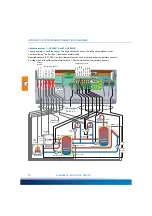
Hydraulic systems and connection diagrams
After entering the installer code, in the menu ›INSTALLER‹ - ›COMMISSIONING‹ - ›cur. scheme‹
select one of the following systems that best fits your setup. “Select hydraulic system” on page 111
Further hydraulic systems
Provides a configured system with more functions than are required for your system (e.g. 3 heating
circuits, although your system has only 2 heating circuits, or no solar system connected):
• Deactivate the non-existent temperature sensors in the ›SENSOR ADJUSTING‹ menu.
“Sensor adjustment” on page 121
• Deactivate the non-existent pumps and mixers in the respective menus of the heating circuits or
heat generators.
Note:
Only 'non-critical' components can be deactivated, i.e. only sensors and pumps/mixers that
are not absolutely necessary for the selected system.
Example: Hydraulic system 10 results from hydraulic system 8: ›HCW 008 Sol‹ by deactivating the
temperature sensor and the pump for the solar system.
• In ›Curr. System‹ in the ›COMMISSIONING‹ menu, select the hydraulic system ›HCW 008 Sol‹.
“Select hydraulic system” on page 111
• In the menu ›COMMISSIONING‹ - ›SENSOR ADJUSTING‹ -›collector temp.‹ deactivate the non-
existent sensor via ›activated: NO‹.
“Sensor adjustment” on page 121
• In the menu ›COMMISSIONING‹ - ›SOLAR UNIT‹ - ›PUMP SETTINGS‹ deactivate the non-exis-
tent pump via ›activated: NO‹.
“Configure solar system” on page 117
This deactivates the functioning of the solar system.
NOTE
Determine the structure and structure of the system when
planning the entire thermal system and compare the design
with the hydraulic system of the heating system controller!
Observe the terminal assignment stored in the selected sys-
tem, as this differs from system to system.
NOTE
The listed systems are NOT assembly instructions and are
incomplete, especially with regard to necessary safety devices
and other components (valves, check valves etc.).

