Emtek EMPowered in8-empwrunty Manual Download Page 24

24

Programming Troubleshooting

*When batteries are replaced. Network Module locks have a real time clock that will be set through the User Interface (UI); 

it is recommended to verify correct  date and time particularly those locks operating under Daylight Saving Time (DST).
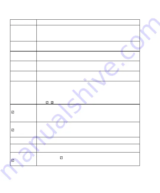
Symptom

Suggested Action

Lock does not respond 

- door is open and 

accessible.

• Touchscreen becomes active when pressed with whole hand. Use larger area of the hand or fingers 

  and verify contact with at least 3 numbers.

• If touchscreen numbers are visible, check to see if they respond when pressed.

• Check batteries are installed and oriented correctly (polarity) in the battery case.

• Check batteries are in good condition; replace batteries* if discharged.

• Check to see if touchscreen harness is fully connected and not pinched.

Lock does not respond 

- door is locked and 

inaccessible.

• Batteries may be completely discharged.

• Apply 9V Battery to terminals below the touchscreen for backup power option.

Unit is on for a while 

then shows no reaction. 

Lights dim.

• Batteries do not have enough power. Replace Batteries*.

Unit Chimes to indicate 

code acceptance, but the 

door will not open.

• Check door gaps for any foreign objects between door and frame.

• Check that the wire harness is firmly connected to the PCB.

Unit operates to allow 

access, but will not auto-

matically re-lock

• Check to see if Auto Re-lock Mode is enabled.

• Disable Auto Re-lock Mode to lock the door (automatically).

• If low battery indicator is lit (see below), change batteries*.

PIN Codes will not 

register.

• PIN Codes must consist of 4 to 8 digits to register.

• The same PIN Code cannot be used for multiple users.

• Registration/management of PIN Codes is set by the authority of the 

   Master Code, which is set first.

• Contact the Master user.

• User Codes must be entered within 5 seconds (while touchscreen is active) or process will have to be 

restarted.

• Check      or      gear cannot be used as part of the PIN Code.

Upon entering a PIN Code 

and pressing         

     key, the unit displays 

“invalid code” error or 

lock times out without 

responding.

• Lockout Mode is enabled.

• Only the Master user can enable/disable Lockout Mode.

• Contact the Master user.

Upon entering a PIN Code 

and pressing the        

     key, the red padlock 

icon appears and there are 

different tones.

• Check to see if the lock is set to Lockout Mode.

• Setting/managing Lockout Mode is done through Master Code only. 

• Contact the Master user.

The unit operates but it 

makes no sound.

• Check to see if Silent Mode is enabled (see Feature #4)

The unit responds “Low 

Battery”

• This is the alert to replace the batteries. Replace all four (4) batteries* 

   with new AA Alkaline batteries.

Upon entering a PIN Code 

and pressing the      

     key, the unit responds 

“Wrong number of digits”.

• The digits entered were incorrect or incomplete. Re-enter the correct code 

   followed by the check      key.

Summary of Contents for EMPowered in8-empwrunty

Page 1: ...EMPoweredTM Motorized Touchscreen Works with Yale Access Keypad Smart Lock Deadbolt WORKS WITH ...

Page 2: ...rews x4 8 x 3 4 Wood Screws x2 10 32 x 1 3 8 Machine Screws x2 10 x 3 Wood Screws Battery Cover Mounting Plate Security Plate Strike Plate AA x4 Batteries Connect Wi Fi Bridge DoorSense Interior Escutcheon Deadbolt Latch 2 3 8 Deadbolt Latch 2 3 4 ...

Page 3: ...3 Door Prep Door Jamb Prep 2 3 8 or 2 3 4 Backset 2 1 8 Diameter Bore 1 8 Deep 2 1 4 1 1 Diameter Edge Bore 3 16 Deep 2 3 4 1 1 8 3 4 1 1 4 1 1 4 Deep ...

Page 4: ...4 Install Latch Strike Plate 1 Note Use only the supplied latch for proper functionality Bolt must be in retracted unlocked position Note horizontal orientation of mechanism ...

Page 5: ...5 Install Touchscreen Escutcheon 2 Outside of the door Inside of the door ...

Page 6: ...6 Install Interior Mounting Plate 3 Loosen screw to remove cover ...

Page 7: ...7 Connect the Cable Assembly 4 ...

Page 8: ...8 Install Interior Escutcheon 5 See comment about reset button on page 26 Resetting Lock to Factory Default ...

Page 9: ...9 Testing Operation 6 ...

Page 10: ...10 1 Determine mounting location 1 1 2 3 1 2 DoorSenseTM Cover DoorSenseTM Housing Mounting Tape Mounting Screws Installing DoorSenseTM Surface Mount Option 7a ...

Page 11: ...11 2 Attach mounting tape then screw into frame Installing DoorSenseTM Surface Mount Option 7a 3 Complete the DoorSense setup in the Yale Access app Lock Settings after completing step 12 ...

Page 12: ...12 1 Remove magnet from housing and place DoorSenseTM Cap onto the magnet DoorSenseTM Housing DoorSenseTM Cap Installing DoorSenseTM Flush Mount Option 7b ...

Page 13: ...3 2 Drill hole and Insert DoorSenseTM 3 1 2 5 8 Diameter 1 2 Deep 3 Complete the DoorSense setup in the Yale Access app Lock Settings after completing step 12 Installing DoorSenseTM Flush Mount Option 7b ...

Page 14: ...14 Bolt must be in retracted unlocked position before installing batteries Install Batteries 8 ...

Page 15: ...ng the lock to factory default Programming and use of lock is not possible until this step has been successfully completed Enter a 4 to 8 digit PIN Code followed by the gear key Registered Press Press Register Master PIN Code Press the gear key to continue Creating Master PIN Code 9 ...

Page 16: ...16 Handing the Lock Activate the Lock OR Handing Lock Handing Lock Complete 10 ...

Page 17: ...red back arrow Conversely you can wait for the menu to time out to exit the menu This completes the registration process for the module If the number 7 does not appear on the keypad it may be due to any of the following reasons 1 The Master PIN Code is not set 2 The module is not properly seating within the lock Press Press Enter Master PIN Code Press the gear key to continue Press 7 and then the ...

Page 18: ... Yale August Connect Wi Fi Bridge 12 SET UP A DEVICE SET UP A DEVICE CAN T SCAN THE CODE CAN T SCAN THE CODE CAN T FIND THE SERIAL NUMBER ENTER SERIAL NUMBER FOUND ON CONNECT BRIDGE OR CAN T FIND THE SERIAL NUMBER EMTEK YALE RADIO MODULE ACCESSORY MD 01 CONNECT WI FI BRIDGE QR Codes Coming Soon QR Codes Coming Soon ...

Page 19: ...19 Install Cover Secure cover by tightening screw on bottom 13 ...

Page 20: ... Lock Response Menu mode enter number press key to continue 3 Enter digit corresponding to the function to be performed followed by the key Follow the voice commands The Master PIN Code must be registered prior to any other programming of the lock Feature Programming Through Menu Mode Using Master PIN Code ...

Page 21: ...French Delete Continue Continue Continue Complete Complete Complete User PIN Code Registration Handing the Lock 1 1 1 1 2 2 1 1 3 3 3 3 3 PIN PIN PIN 2 5 Volume Settings 4 Language Setting Mode 5 Lockout Mode 6 Network Module Setting 7 Complete Disable Enable Enable Disable Disable 30 sec 60 sec 2 min 3 min Continue Advanced Lock Settings Automatic Re lock Inside Indicator Light One Touch Locking ...

Page 22: ... the Low Battery Warning indicator flashes RED If battery power is completely lost use the 9 Volt battery override To use the 9V battery override apply 9V battery in either direction to terminals below the touchscreen for backup power option Wake up the lock and enter your PIN Code to unlock the door Master PIN Code The Master PIN Code is used for programing and for feature settings It must be cre...

Page 23: ...alarm sounds if attempting to forcibly remove outside lock from door User PIN Code The User Code operates the lock Maximum number of User Codes is 250 with Network Module without Network Module maximum is 25 User Codes Note When deleting User Code s screen will display User Number not code being deleted Volume Setting Mode The volume setting for PIN Code verification is set to Low 2 by default oth...

Page 24: ...t will not auto matically re lock Check to see if Auto Re lock Mode is enabled Disable Auto Re lock Mode to lock the door automatically If low battery indicator is lit see below change batteries PIN Codes will not register PIN Codes must consist of 4 to 8 digits to register The same PIN Code cannot be used for multiple users Registration management of PIN Codes is set by the authority of the Maste...

Page 25: ...y made to bolt c Verify proper door preparation and re bore holes that are too small or misaligned d Verify keypad wire harness is routed under the bolt see Fig A e Verify bolt is installed with correct side up Fig A NOTE TO INSTALLER AND CONSUMER While EMTEK has included several features to prevent lockout 9V battery jumper low battery warnings it is still possible for a lockout situation to occu...

Page 26: ...er programming of the lock When lock is reset to factory defaults all User Codes including the Master PIN Code are deleted and all programming features are reset to original default settings see below 1 Remove battery cover and batteries 2 Remove the interior escutcheon to access the reset button 3 The reset button see page 8 Step 5 is located beside the PCB cable connector 4 While pressing the re...

Page 27: ...could void the user s authority to operate this equipment This transmitter must not be co located or operating in conjunction with any other antenna or transmitter Radiation Exposure Statement This equipment complies with FCC radiation exposure limits set forth for an uncontrolled environment This equipment should be installed and operated with minimum distance 20cm between the radiator your body ...

Page 28: ...tate of California to cause cancer and birth defects or other reproductive harm For more information go to www P65Warnings ca gov Copyright 2021 EMTEK Products Inc an ASSA ABLOY Group company All rights reserved Reproduction in whole or in part without the express written permission of EMTEK Products Inc is prohibited ...

Reviews: