EMS SBR FX-15000/RMD User Manual Download Page 5

3

Software

3.1 General Configuration

To review or change the IP configuration, you
can access SBR-FX/RMD using a terminal
program connected to its RS232 port.

- Connect a serial cable to the RS232 port of
SBR-FX/RMD.

- Connect the other end to a free COM port of
your PC.

Note: The serial cable should have the
pins 2 and 3 crossed and pins 5 connected
directly.

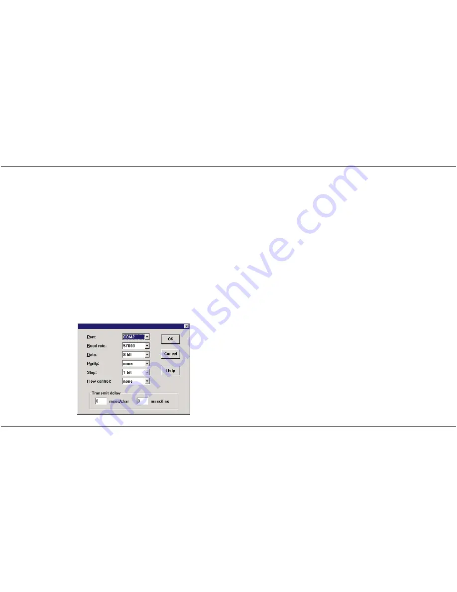
- Start your terminal software. Configure your
software for a direct connection using the PC’s
COM port. See the communication parameters
to use in the following image.

SBR-FX/RMD

User Manual

EMS Dr. Thomas Wünsche

5

Notice that the ‘flow control’ parameter within
the serial monitor running on the PC has to be
turned off. If this parameter can not be chan-
ged, supplemental bridges (between pins 4-6
and pins 7-8) have to be inserted on the PC
sided connector of the serial cable described
above.

- Power on SBR-FX/RMD

- On the terminal window you will see the out-
put from the startup procedure. If the procedu-
re was successful, you will see a prompt that
enables you to input commands.

- Enter the command

fltool -r IP

to inqui-

re the IP address.
- Enter the command

fltool -r HOSTNAME

to inquire the HOSTNAME.
- Enter the command

fltool -r NETMASK

to inquire the NETMASK.

- To change the IP configuration, you can use
the same application, but with the parameter
‘-w’. Examples:

fltool -w IP 192.168.0.93
fltool -w HOSTNAME sbr1
fltool -w NETMASK 255.255.255.0

The IP configuration information is stored wit-
hin the flash of SBR-FX/RMD. The parameters
become valid after a reboot.

User Manual

SBR-FX/RMD

6

EMS Dr. Thomas Wünsche

Summary of Contents for SBR FX-15000/RMD

Page 1: ...r written agreement from EMS Dr Thomas Wünsche For technical assistance please contact EMS Dr Thomas Wünsche Sonnenhang 3 D 85304 Ilmmünster Tel 49 8441 490260 Fax 49 8441 81860 Email support ems wuensche com Our products are continuously improved Due to this fact specifications may be changed at any time and without announcement WARNING SBR FX RMD hardware and software may not be used in applicat...

Page 2: ... Startup Configuration 8 4 Electrical Characteristics 11 4 1 Absolute Limiting Values 11 4 2 Nominal Values 12 5 Operating Instructions 13 5 1 Connection Scheme 13 5 2 Router Correction Time and Cascading 14 5 3 ESD Precaution 15 SBR FX RMD User Manual EMS Dr Thomas Wünsche iii THIS PAGE INTENTIONALLY LEFT BLANK User Manual SBR FX RMD iv EMS Dr Thomas Wünsche ...

Page 3: ...linked back to back the trans mission protocol used on the optical fiber is the UDP IP protocol The use of UDP IP abo lishes the length datarate restrictions between two CAN bus segments Depending on the type of the device extensions up to 15km or 40km are possible SBR FX RMD automatically detects the baud rate on the controlling side The I O side can be run with the baudrate detected on the con t...

Page 4: ...n SBR FX RMD only applicable LED states are listed SB Active blinking traffic on the CAN bus FX Active blinking traffic on the optical link FX Link on devices have been connected via the optical link Status1 blinking logical connection between devices in progress on logical connection established Status2 blinking SafetyBUS initialization in progress on SafetyBUS communication OK SBR FX RMD User Ma...

Page 5: ...f this parameter can not be chan ged supplemental bridges between pins 4 6 and pins 7 8 have to be inserted on the PC sided connector of the serial cable described above Power on SBR FX RMD On the terminal window you will see the out put from the startup procedure If the procedu re was successful you will see a prompt that enables you to input commands Enter the command fltool r IP to inqui re the...

Page 6: ...nd with just 2 quotation marks SBR FX RMD User Manual EMS Dr Thomas Wünsche 7 Example fltool w USER_x 3 2 SafetyBUS p Startup Configuration The software running on SBR FX RMD devi ces is started upon boot time and normally needs no intervention from the user It is however possible to modify application start parameters This is useful to change from automatic baudrate detection default to a fixed b...

Page 7: ...filtering must be activated on both sides master and slave Example for a master with IP 192 168 0 93 connecting to a slave with IP 192 168 0 94 and fixed baudrate Master fltool w USER_1 sdtpsrv dest ip 192 168 0 94 w Slave fltool w USER_1 sdtpsrv dest ip 192 168 0 93 b 500 w Please notice that the commands have to be written into a single line without the SBR FX RMD User Manual EMS Dr Thomas Wünsc...

Page 8: ...on bus connections 30 30 V SBR FX RMD User Manual EMS Dr Thomas Wünsche 11 4 2 Nominal Values Parameter Min Typ Max Unit Current consumption 80 200 mA Supply voltage 20 24 30 V Optical damping SBR FX15000 13 dB Optical damping SBR FX40000 4 28 dB Admissible fiber length SBR FX15000 15 km Admissible fiber length SBR FX40000 40 km All values unless otherwise specified refer to a supply voltage of 24...

Page 9: ...iving data line 3 TXD Sending data line 4 DTR Currently not supported 5 GND Ground 6 DSR Currently not supported The optical connection is realized by a pair of single mode fibers 9 125µm diameter con nected via LC terminals 5 2 Router Correction Time and Cascading The values listed below are typical values and should fit most system configurations The va lues to be used in a specific system may v...

Page 10: ...5 3 ESD Precaution As an ESD precaution the RS232 cable may only be connected during configuration of the device and not at normal operating time SBR FX RMD User Manual EMS Dr Thomas Wünsche 15 ...

Reviews: