background image


3

Safety Information 

This equipment generates, uses, and can radiate radio frequency energy and, if not installed and used in 

accordance with the instructions, may cause harmful interference to radio or television reception. However, 

there is no guarantee that interference will not occur in a particular installation. If this equipment does cause 

interference to radio and television reception, which can be determined by turning the equipment off and on, 

the user is encouraged to try to correct the interference by one or more of the following measures: 


Reorient or relocate the receiving antenna; 


Increase the separation between the equipment and receiver; 


Connect the equipment into an outlet on a circuit from that to which the receiver is connected. 


Caution


To prevent fire, shock hazard, or interference, only use the recommended accessories. To prevent electric 

shock, do not use the plug with an extension cord, receptacle, or other outlet unless the blades can be fully 

inserted to prevent blade exposure. To reduce the risk of electric shock, do not remove the unit cover or back. 

There are no serviceable parts inside. Refer servicing to a qualified personnel only. 


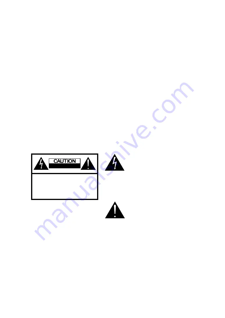
RISK OF ELECTRIC SHOCK 

                      DO NOT OPEN


CAUTION: TO REDUCE THE RISK OF ELECTRIC SHOCK 

 DO NOT REMOVE COVER 

NO USER-SERVICEABLE PARTS INSIDE 

REFER SERVICING TO QUALIFIED SERVICE PERSONNEL 


This symbol is intended to alert the 
user to the presence of uninsulated

dangerous voltage within the product’s

enclosure that may be of sufficient

magnitude to constitute risk of fire or

electric shock


This symbol is intended to alert the user

to the presence of important operating

and 

maintence instructions

 in the

literature accompanying this

 product 

Summary of Contents for HD-3202

Page 1: ...VISION 6 SUPPLIED ACCESSORIES 6 TV CONTROL FUNCTIONS 7 SETTING UP THE REMOTE CONTROL 8 REMOTE CONTROL FUNCTIONS 9 INPUTS AND OUTPUTS 10 SETTING UP YOUR TELEVISION 19 CHANGING THE SOURCE 19 ASPECT 20 A...

Page 2: ...turning the equipment off and on the user is encouraged to try to correct the interference by one or more of the following measures Reorient or relocate the receiving antenna Increase the separation b...

Page 3: ...so If you drop this device on the floor while moving it please inform service office immediately to get a safety checking In order to avoid firing and property damage as the consequence please do not...

Page 4: ...Caution To prevent fire shock hazard or interference only use the recommended accessories To prevent electric shock do not use the plug with an extension cord receptacle or other outlet unless the bla...

Page 5: ...sure the power cord from the AC outlet is unplugged and disconnect from the antenna if the TV is left unattended and unused for a long period This will prevent damages to the TV lighting and power lin...

Page 6: ...when handling the screen Do not use glue or adhesive tape on the screen Do not write on the screen Do not allow the screen to come in contact with any hard objects Do not allow condensation to form on...

Page 7: ...6 Introduction Your Television Supplied Accessories The following items come along with your LCD TV...

Page 8: ...CH Press to change channel when is menu mode these acts as navigation keys 4 VOL Press to adjust the volume when is menu mode these acts as navigation keys 5 SOURCE Video input selection Press this bu...

Page 9: ...l 2 Insert two AAA batteries Use the and marks to guide you The marks on your batteries correspond to the marks on the compartment The marks on your battery correspond to the marks on the compartment...

Page 10: ...Press this key to display the video source selection menu 11 FAVORITE Press to switch your favorite channels 12 ASPECT Choose from widescreen 4 3 video 16 9 zoom More details on Page20 13 SLEEP Activa...

Page 11: ...DMI A V Cable Available Interface Description Recommended Devices 1 Power Input AC 120V 2 SVC Service connector Maintenance use only 3 Audio Outputs Contains composite video SPDIF and one pair of R L...

Page 12: ...coaxial cable 75 ohms for connecting TV signal from your antenna or cable TV provider to the tuner input 3 4 Connect the power cord of the LCD TV to a power outlet 5 Press the SOURCE button on either...

Page 13: ...ble television outlet choose Cable For more information on the Channel menu refer to Page 23 7 Then choose STD and press OK STD Standard HRC Harmonic Related Carrier IRC Incremental Related Carrier 8...

Page 14: ...your digital set top box to the HDMI COMPONENT or S VIDEO input jacks in the rear of the LCD TV 3 Use the AUDIO cables to connect the AUDIO L R output jacks of your digital set top box to the AUDIO L...

Page 15: ...hanging the source refer to Page19 Note 1 It is strongly recommended that the user connects Digital Set Top Box via HDMI connection if provided HDMI signal is pure digital signal therefore it gives th...

Page 16: ...Connect the red Pr Cr jack on the back of your DVD player to the red Pr Cr jack on the rear of the LCD TV 3 Connect the blue Pb Cb jack on the back of your DVD player to the blue Pb Cb jack on the rea...

Page 17: ...sly 1 Connect the S video on the back of your camcorder to the S video under AV Input jack 2 Connect the audio red R and white L on the back of camcorder to the audio red R and white L jacks on the re...

Page 18: ...C connector on the rear of the LCD TV 2 Connect the audio output on your PC to the PC audio input on the rear of the LCD TV 3 Press the SOURCE button on the remote control to select VGA 4 You may conf...

Page 19: ...jack of your external device to the HDMI input jack in the rear of the LCD TV 1 Press the SOURCE button on either the remote control or the TV controls Select HDMI Changing the source refer to Page 1...

Page 20: ...s the SOURCE button on either the remote control or TV controls 2 Repeat it according to selecting until wanting of source TV AV1 CVBS AV1 S Video YPbPr1 YPbPr2 HDMI VGA Note When the source has no si...

Page 21: ...torts image by stretching the whole image horizontally In most cases widescreen videos such as DVD movies widescreen modes will have black spots on the top and the bottom of the screen this is called...

Page 22: ...ote control to start the OSD menu 2 Use to navigate through the main function 3 Press or OK to enter the highlighted category 4 Use to navigate 5 Press MENU or to change the selected settings 6 Press...

Page 23: ...UNER MODE AUTO SCAN CHANNEL EDIT SIGNAL STRENGTH EXTERNAL INPUT PICTURE PICTURE MODE BRIGHTNESS SATURATION CONTRAST SHARRNESS TINT RGB COLOR TEMP DNR BACKLIGHT CONTROL SOUND SOUND MODE TREBLE BASS BAL...

Page 24: ...arch for available channels on television Start Stop Channel Edit This option allows the user to add delete recognized channels ADD DELETE Favorite Signal Strength User can recognize the signal streng...

Page 25: ...Press MENU button to switch to previous step on the menu screen 1 Press MENU button 2 Use button to highlight Channel icon then press OK 3 Use button to make a choice from Air or Cable then press OK 4...

Page 26: ...n press OK 3 Choose the Air and press OK 4 Use button to highlight Auto Scan icon then press OK Scan Digital channel after Analog channel finish 5 It will automatically scan and store all of the chann...

Page 27: ...light Channel icon then press OK 3 Press button to highlight channel Edit icon then press OK 4 Use button to select channels Selected channels will be yellow colored Then press OK button to add or del...

Page 28: ...More than 80 no problem in watching TV Press EXIT to exit the menu screen Press MENU button to switch to previous step on the menu screen 1 Press MENU button 2 Use button to highlight Channel icon the...

Page 29: ...ser While adjusting customized selections only the selection and its status bar will be shown on the screen Example 1 Use or to Picture Mode and press OK 2 Use or to User and press OK 3 Press to brigh...

Page 30: ...lor 10 10 RGB This option allows user to adjust R G B Value Separately R 0 100 G 0 100 B 0 100 Color Temp This option allows the user choose among three styles of displaying colors COOL The colors of...

Page 31: ...ass Adjusts the lower pitched sounds 0 100 Balance Adjusts the position of the sound The negative end represents that the sound will lean towards the left and the positive end represents that the soun...

Page 32: ...nd press OK or 4 When the Enter PIN box pops up enter the 4 digit password The default password is 0000 Set Blocking 1 After get released use button to highlight Set Blocking icon then press OK 2 Use...

Page 33: ...ating icon then press OK 2 Use button to make a choice then press OK G PG PG 13 R NC 17 X NR TV Y For all children TV Y7 For children above 7 TV G For anyone TV PG children can watch with guardian TV...

Page 34: ...on the menu screen DTV Rating 1 Use button to highlight DTV Rating then press OK This function works only in DTV input Setup Code 1 Use button to highlight Setup Code then press OK 2 When the box pop...

Page 35: ...Use button to highlight Functions icon then press OK 3 Use button to highlight Caption icon then press OK 4 Use button to highlight Display Always On or Off then press OK 5 When Display is Always On u...

Page 36: ...or opacity then press Can choose other forms then press OK Color Auto Black White Red Green Blue Yellow Mangenta Cyan Opacity Auto Solid Flashing Translucent Transparent Caption Option 1 Use button t...

Page 37: ...n Blue Yellow Mangenta cyan Italic Auto On Off Underline Auto On Off Press EXIT to exit the menu screen Press MENU button to switch to previous step on the menu screen Caption Text 1 Use button to hig...

Page 38: ...K 4 Choose the Manual then press OK 5 Use button to set for Date Time Power on Time 1 Press Menu Button 2 Use button to highlight Setup then press OK 3 Use button to highlight Power on Time then press...

Page 39: ...he follows Off Daily Once 5 Choose the Time then press OK The user can set the time of power off Sleep 1 Press MENU button 2 Use button to highlight Setup icon then press OK 3 Use button to highlight...

Page 40: ...ghlight Setup then press OK 3 Use button to highlight Menu Opacity then press OK 4 Use button to set for Menu Opacity Emergency Alert 1 Press MENU Button 2 Use button to highlight Setup then press OK...

Page 41: ...er can adjust horizontal position 6 Choose the Ver Center then press SELECT User can adjust vertical position 7 Choose the Phase then press SELECT User can adjust the input sampling phase for precise...

Page 42: ...na reception strength may be weak 2 Reposition the antenna s placement 3 Make sure the antenna cable is properly connected to the LCD TV set Color abnormal or improper 1 Check the color adjustment in...

Page 43: ...ake sure the volume level is not set to the minimum 2 Make sure the mute function is not selected The picture is not sharp 1 The program reception may be weak 2 Check the Sharpness setting in the OSD...

Page 44: ...nna input 75 Audio Built in speaker 10W X 2 Color Temperature Normal Warm Cool Screen Size adjustment Normal Zoom Wide Progressive Scan Yes Compatibility 3 2 pull down Yes Color system NTSC SDTV HDTV...

Page 45: ...44 Pictures for different crust...

Page 46: ...ut 720p 50 60 480i 60 480p 60 1080i 60 Component Y PbCb PrCr 720p 60 P positive N negative Source Resolution Refresh Rate Hz Horizontal Frequency Khz Vertical Frequency Hz Horizontal Sync Polarity TTL...

Reviews: