background image

25663-0-0309

Page 49

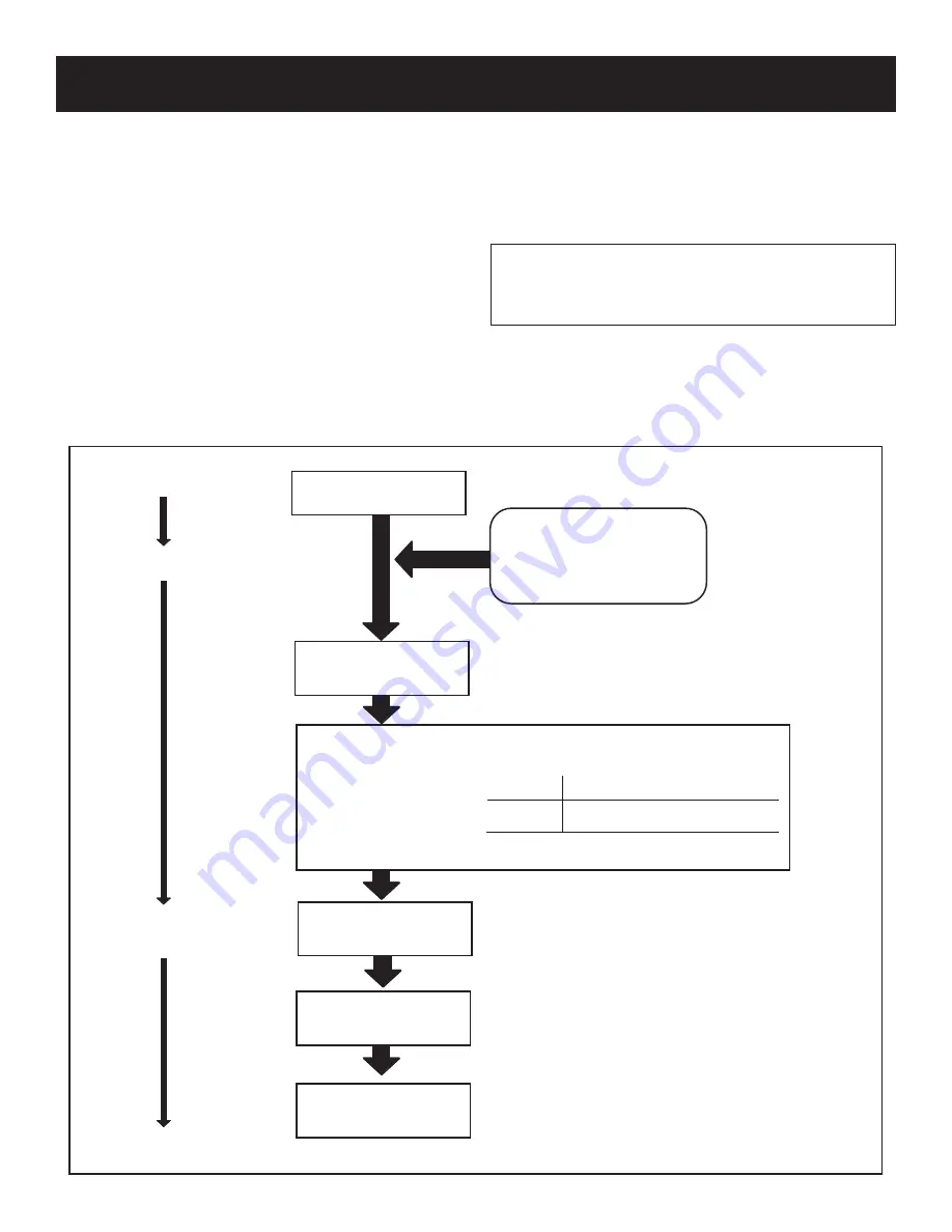
Spark Generator Powered

First Valve (Pilot)

Operator Opens

Pilot burner lights.

Module senses flame current.

PILOT BURNER OPERATION

MODULE
S8600H

* Lockout timing is stamped on module.

RESPONSE
After 90 seconds*pilot valve

closes, spark stops.

OR

IF FLAME CURRENT SENSED

Spark generator off

Second valve operator

(Main) opens.

MAIN BURNER OPERATION

Module monitors pilot

flame current.

THERMOSTAT SATISFIED

Valves close. Pilot and

main burners are off.

START

STAGE 1

Trial for Ignition

STAGE 2

Main Burner

Operation

END

S8600H NORMAL OPERATING SEQUENCE

Pilot burner does not light

Thermostat, Wall Switch,

Remote, Etc. Calls for Heat

POWER INTERRUPTION

System shuts off. Restarts when

power is restored.

PILOT FLAME FAILURE

Second main operator closes.

Module starts trial for ignition.

safety lockout

S8600H provides 100 percent shutoff, or safety lockout.  A timer 

starts timing the moment the trial for ignition starts.  Ignition spark 

continues only until the timed trial for ignition period ends.  Then 

the module goes into safety lockout.  Lockout de-energizes the 

first main valve operator and closes the first main valve in the gas 

control, stopping pilot gas flow.  The control system must be reset 

by setting the thermostat below room temperature for one minute 

or by turning off power to the module for one minute.

Main Burner operation

When the pilot flame is established, a flame rectification circuit 

is completed between the sensor and burner ground.  The flame 

sensing circuit in the module detects the flame current, shuts off the 

spark generator and energizes the second main valve operator.  The 

second main valve opens and gas flows to the main burner, where 

it is ignited by the pilot burner.  The flame current also holds the 

safety lockout timer in the reset (normal) operating condition.
When the call for heat ends, both main valve operators are de-en-

ergized, and both main valves in the gas control close. 

caUtion:

    Label  all  wires  prior  to  disconnection  when 

servicing  controls.  Wiring  errors  can  cause  improper  and 

dangerous operation. Verify proper operation after servicing.

interMittent pilot troUBleshootinG

Summary of Contents for Tahoe DVP36FP30-4LP

Page 1: ...ng plate This appliance is not convertible for use with other gases unless a certified kit is used The Tahoe Direct Vent Zero Clearance Gas Fireplace Heater GAS FIRED Installer Leave this manual with...

Page 2: ...F Flex Vent Instructions 37 Vertical Termination 38 39 Log Placement 4 Log Set 40 Operating Instructions 41 42 Standing Pilot Wiring Diagram 43 Standing Pilot Lighting Instructions 44 Standing Pilot T...

Page 3: ...front or any part removed for servicing the appliance must be replaced prior to operating the appliance Work should be done by a qualified service person Keep burner and control compartment clean Vent...

Page 4: ...perform service or make adjustments in an area where the conditions are such that you may not detect the odor if there has been a leak of LP Gas Odor fade due to oxidation by rust or adsorption on wal...

Page 5: ...isions shall comply with NFPA 720 and be ANSI UL 2034 listed and IAS certified 3 SIGNAGE A metal or plastic identification plate shall be permanently mounted to the exterior of the building at a minim...

Page 6: ...f local codes with the National Fuel Gas Code ANSI Z223 1 NFPA 54 Natural Gas and Propane Installation Code or CSA B149 1 in Canada Available from the American National Standards Institute Inc 11 West...

Page 7: ...al Vent Kit DVVK 4F Horizontal Flex Vent Kit 4 Flex DVVK 4RE Horizontal Round Termination wall thickness up to 11 7 16 DV822 Vinyl Siding Kit for DVVK 4RE DVVK 4FV Vertical Flex Vent Kit DVEK 10 10 Ve...

Page 8: ...ns a minimum of 6 inches clearance must be maintained from the perpendicular wall and the front edge of the appliance Figure 2 Combustible Material No greeting cards stockings or ornamentation of any...

Page 9: ...ttention If one of the procedures results in pressures in excess of 1 2 psig 14 w c 3 5 kPa on the fireplace gas valve it will result in a hazardous condition Checking Manifold Pressures Both Propane...

Page 10: ...te located on the back of the fireplace These will be used to close the top flue and inlet openings 3 Insert the insulation retainer bracket and insulation into the top flue pipe before reinstalling t...

Page 11: ...l strip and then screw into pre drilled holes on fireplace side Measure from face of fireplace to face of drywall strip to determine final depth Figure 8 Vent Pipe Clearance Note Maintain one inch 1 o...

Page 12: ...s facing to the fireplace surround Flush Mount Mantel Installation Figure 11 The fireplace must extend 3 4 beyond finished wall surface when using a flush mount mantel Refer to Figure 11 to locate nai...

Page 13: ...following surfaces 1 A flat hard combustible burnable surface 2 A raised wooden platform 3 Four 4 corner supports Example Four 4 concrete masonry blocks These supports must be positioned so they cont...

Page 14: ...15 3 4 7 3 4 to 9 1 4 12 17 1 4 to 18 3 4 10 3 4 to 12 1 4 VENT CAP WALL FIRESTOP THIMBLE INSTALLATION continued Horizontal only straight out the back Figure 16 vertical 90 elbow to horizontal out th...

Page 15: ...run the length of the horizontal run MUSTbe reduced by 18 45cm This does not apply if the 45 degree elbows are installed on the vertical part of the vent system Reduce 3 for every 90 elbow Example Acc...

Page 16: ...he 7 178mm is measured from the center of the horizontal vent pipe as it penetrates through the wall Ensure the sidewall venting clearances are observed If venting system is installed below ground we...

Page 17: ...high x 10 254mm wide with its center line determined by the amount of vertical rise and horizontal run of the termination See Figure 24 When locating the hole it must be noted that the bottom of the...

Page 18: ...alified field service person Inspect the external vent cap on a regular basis to make sure that no debris is interfering with the airflow In spect entire venting system to ensure proper function Pleas...

Page 19: ...ertical Flex Termination Kit WARNING Ensure that the venting system exits the structure through the roof and does not terminate less than 12 inches 305mm above the roof WARNING Refer to your fireplace...

Page 20: ...nough to provide a mini mum 1 air space clearance from the vertical vent pipe to any combustible framing 6 Install the Firestop Thimble assembly to the framed opening in the ceiling using common nails...

Page 21: ...oof cutout opening see step 5 Feed the flex vent end down through the roof opening and firestop thimble assembly installed in steps 4 through 6 14 Secure the roof support assembly to the roof sheathin...

Page 22: ...tic insulation shield The collar can be installed around the flex pipe or hard pipe just above the firestop thimble This collar will act as a shield to prevent blown in sulation from entering the thim...

Page 23: ...Thimble Ceiling Straps As Req d Venting Support With Gasket Clamps 7 Dia Adapter Collar 4 Dia Flue Connector Assembly Firestop Thimble Adjustable Storm Collar Use TO Keep Insulation Out Of Inlet Vent...

Page 24: ...er by 6 ft MF07ALA2F006 1 5 4 7 x 48 Rigid Pipe Assembly MF100554 1 6 Firestop Thimble Assembly MF100124 1 7 Roof Flashing 0 12 to 6 12 MF100091 1 8 7 Flex Adapter Collar with Gasket MF100524 1 9 7 St...

Page 25: ...25663 0 0309 Page 25 Figure 34 Figure 35 Figure 36 24 24 MINIMUM CLEARANCE TO COMBUSTIBLES EXAMPLES TOP VENT RUN LP and Nat models LP and Nat models LP and Nat models...

Page 26: ...with same EXAMPLE A If the vertical dimension from the floor of the unit is 12 feet 4 inches the horizontal run to the outer wall flange must not exceed 12 feet 3 inches EXAMPLE B If the vertical dime...

Page 27: ...Page 27 Figure 38 Figure 39 Figure 40 Figure 41 Model Maximum Pipe Length H1 DVP36 24 Model Maximum Pipe Length H1 DVP36 24 EXAMPLES REAR VENT RUN Nat models only Nat models only Nat models only Nat...

Page 28: ...ace in such a way that minimizes the number of offsets and horizontal vent length Since it is very important that the venting system maintain its balance between the combustion air intake and the flue...

Page 29: ...r line of the regulator I clearance to service regulator vent outlet 6 feet 1 8m minimum J clearance to non mechanical air supply inlet to building or the combustion air inlet to any other appliance 1...

Page 30: ...vent component is securely fitted and locked into the preceding component in the vent system Figure 44 WALL THIMBLE MAXIMUM OF THREE 90 ELBOWS MAXIMUM OF TWO 90 ELBOWS Special venting components Simps...

Page 31: ...the 10 inch x 11 inch hole previously cut Secure with nails or screws The heat shields of the firestops MUST BE placed towards the top of the hole Continue the vent run through the firestops See Figu...

Page 32: ...25663 0 0309 Page 32 Figure 49 See Horizontal Termination Page 33 and Vertical Termination Page 38 39 FRAMING AND FINISHING continued Figure 47 Figure 48...

Page 33: ...vinyl siding standoff The vinyl siding standoff will be installed between the vent terminationandtheexteriorwall SeeFigure50 Thishorizontalvent terminationboltsontotheflatportionofthevinylsidingstand...

Page 34: ...or not the extension thimble is to be used If the combustible wall depth is over 5 3 8 137mm then the extension thimble should be used Figure 1 3 Install the wall thimble assembly through the framed o...

Page 35: ...id venting system using 3 self tapping screws 12 Seal the 4 102mm diameter flue outlet tube Follow instructions and diagram Figure 56 13 Fasten4 102mm diameterflueoutlettubeinplace Donot twist the flu...

Page 36: ...high temperature sealant to the opposite end of the tube on the inside of the tube The end with the gasket will attach to the back of the unit Continue with Step 13 Connecting to Rigid Vent System If...

Page 37: ...Firestop Thimble assembly as required through the wall Refer to the venting charts in the fireplace manual to determine the proper height and size of the vent opening The minimum opening should be 9 w...

Page 38: ...eaks and in extreme cases holes These components should immediately be replaced 2 Remove the cap and shine a flashlight down the vent Remove any bird nests or other foreign material 3 Check for eviden...

Page 39: ...ceineither the vertical or horizontal position replace horizontal and vertical pipe lengths elbows and horizontal or vertical termination kit Allventsystemcomponentslockintoplacebyslidingtheconcentric...

Page 40: ...2 left front pins on burner pan 6 Place right front 3 log onto two 2 right front pins on burner pan 7 Place Branch 4 onto one 1 pin on rear log 8 Place decorative rock in front of grates and sides of...

Page 41: ...millivolts electrical current to build up to a sufficient level allowing the gas control to operate properly 1 Follow the SAFETY and LIGHTING INSTRUCTIONS for standing pilot controls found in this ma...

Page 42: ...e remote and immediate heat is desired turn the REMOTE OFF ON switch from the REMOTE position to the ON position Electric 120 volt Operated Remote Control FREC Connectthegreenandred strippedandbare wi...

Page 43: ...25663 0 0309 Page 43 Figure 66 OPTIONAL THERMOSTAT OPTIONAL WALL SWITCH STANDING PILOT WIRING DIAGRAM...

Page 44: ...ace FOR YOUR SAFETY READ BEFORE LIGHTING Warning If you do not follow these instructions exactly a fire or explosion may result causing property damage personal injury or loss of life A This appliance...

Page 45: ...flame Be sure the wire connections from the thermopile at the gas valve terminals are tight and the thermopile is fully inserted into the pilot bracket Check the thermopile with a millivolt meter Tak...

Page 46: ...ection when servicing controls Wiring errors can cause improper and dangerous operation Verify proper operation after servicing Figure 67 Providedontheintermittentpilotwiringharnessaretwo 2 stripped a...

Page 47: ...ician to inspect the appliance and to replace any part of the control system and any gas control which has been under water Lighting Instructions 1 Stop Read the safety information above 2 Set the the...

Page 48: ...n the gas line to the appliance D Do gas leak test ahead of gas control if piping has been disturbed Gas Leak Test Paint pipe joints with rich soap and water solution Bubbles indicate gas leak Tighten...

Page 49: ...the timed trial for ignition period ends Then the module goes into safety lockout Lockout de energizes the first main valve operator and closes the first main valve in the gas control stopping pilot g...

Page 50: ...heavily insulated wire A Close the manual gas valve B Disconnect the ignition cable at the SPARK terminal on the module Warning Whenperformingthefollowingsteps donottouchstripped end of jumper or SPAR...

Page 51: ...25663 0 0309 Page 51 INTERMITTENT PILOT TROUBLESHOOTING continued...

Page 52: ...nor mal operation after a one minute delay ChecktransformerandAClineforproper input voltage to the control Check with full system load on the transformer 6 2 Failed trial for ignition resulting in loc...

Page 53: ...and modulates such that heat output equals heat loss from the room Auto mode Flame fan are controlled automatically Self powered millivolt control No external power required to control gas valve and...

Page 54: ...a heated living space to make sure that the main burner is not on continuously On Mode When the control is in the ON mode the flame and fan levels and the delay timer are changed with the UP and DOWN...

Page 55: ...25663 0 0309 Page 55 Figure 69 RF WIRING DIAGRAM...

Page 56: ...to the appliance if applicable FOR YOUR SAFETY READ BEFORE LIGHTING WARNING IF YOU DO NOT FOLLOW THESE INSTRUCTIONS EXACTLY A FIRE OR EXPLOSION MAY RESULT CAUSING PROPERTY DAMAGE PERSONAL INJURY OR L...

Page 57: ...d other airborne particles to cling to the glass surface Also initial paint curing may deposit a slight film on the glass It is therefore recommended that the glass be cleaned two or three times with...

Page 58: ...9 31 30 24 33 32 34 40 38 42 39a 36a 37a 41 52 39b 34 33 32 24 30 29 28 27 31 36b 44 46 37b 33 34 32 36c 37c 31 29 28 27 24 23 30 48 49 50 51 47 45 15 26 26 26 43 MILLIVOLT BURNER ASSEMBLY INTERMITTEN...

Page 59: ...JUNCTION BOX ASSEMBLY 14 R 3492 RECEPTACLE 3 PRONG 15 17357 JUNCTION BOX SHIELD 16 17445 TOP SHIELD 17 18806 INNER TOP HEAT SHIELD 18 23343 BAFFLE FLUE VENT 19 18807 LOUVER ASSEMBLY UPPER 20 18809 GL...

Page 60: ...AT 36c R 6115 VALVE RF GAS LP 37a 17161 VALVE BRACKET SIT 37b 17795 VALVE BRACKET IP 37c 17796 VALVE BRACKET RF 38 16223 SPRING LATCH ASSEMBLY 39a R 3435 WIRING HARNESS SIT 39b R 5751 WIRING HARNESS I...

Page 61: ...able speed blower assembly is completed Wiring The appliance when installed must be electrically grounded in accordance with local codes or in the absence of local codes with the National Electrical C...

Page 62: ...10 VOLT AC JUNCTION BOX WHITE SPEED CONTROL FAN SWITCH GROUND BLACK FAN 1 FBB4 BLOWER ASSEMBLY COMPLETE 2 R7649 FAN CONTROL 3 R4192 SPEED CONTROL KNOB 4 R4186 SPEED CONTROL FBB4 OPTIONAL VARIABLE SPEE...

Page 63: ...l with the grout lines on the side brick panels Place the top brick panel into brick panel holder With needle nose pliers carefully bend hold down tabs on brick panel holder over the edges of the top...

Page 64: ...nels were designed to enhance the appearance of your fireplace imitating the look of authentic masonry HERRINGBONE DVP36D2H Simulated Brick Panels The simulated brick panels were designed to enhance t...

Page 65: ...Parts Heater Hearth and Grills Victor Division of F W Webb Company 200 Locust Street Hartford CT 06114 Phone 860 722 2433 Toll Free 800 243 9360 Fax 860 293 0479 Toll Free Fax 800 274 2004 Websites ww...

Page 66: ...25663 0 0309 Page 66 SERVICE NOTES...

Page 67: ...25663 0 0309 Page 67 SERVICE NOTES...

Page 68: ...25663 0 0309 Page 68 Empire Comfort Systems Inc 918 Freeburg Ave Belleville IL 62220 PH 618 233 7420 or 800 851 3153 FAX 618 233 7097 or 800 443 8648 info empirecomfort com www empirecomfort com...

Reviews: