background image

5

1. DESIGN FEATURES

CAR AUDIO AMPLIFIER

: This EMPHASER amplifier allows the cross-over controlled amplifica-

tion of satellite speaker systems, kickwoofer or subwoofer systems

DASH-MOUNT REMOTE LOWPASS LEVEL CONTROL

: This amplifier comes complete with

a compact remote "Lowpass-Level" control unit, which can be conveniently mounted on or under the
dashboard of your car. This control device allows the individual level adjustment of the volume level
(applicable for the lowpass operated channels)

MOSFET POWER SUPPLY

: This EMPHASER amplifier features a beefy MOS-FET power supply,

to boast very high power output. The EA4150 is equipped with two independent power supplies, to
prevent cross interference of the channel pairs 1/2-CH and 3/4-CH

1 OHM IMPEDANCE LOAD STABILITY

: The channels of this amplifier are stable into 1 ohm

loads. Furthermore, the output stage layout provides a very high damping factor and thus, the ampli-
fier will exhibit full control over the connected speaker system(s)

INTEGRATED ELECTRONIC FREQUENCY FILTERING CONTROLS

: The internal crossover

section features independently selectable highpass, lowpass or bandpass filtering, as well as fulllran-
ge loop through. All internal active filters feature crossover slope rates of 12 dB/octave

UNCOMPROMISING DESIGN AND CONSTRUCTION

: Only best electrical and electronic

components found their way into this amplifier, for example double-sided glass-fiber epoxy circuit
boards equipped with high current output devices. The power input side features molded 35mm

2

ter-

minals for full unrestricted current flow

ADVANCED PROTECTION CIRCUITRY

: The protection circuitry safe-guards the amplifier from

short-circuits at the speaker outputs, DC offset voltage at the outputs and overheating of power elec-
tronics

STATUS AND PROTECTION LED'S

: A green and a red LED enable you to easily monitor the

operating status of your EMPHASER amplifier. The LED's are signaling normal operation and pro-
blems, such as short-circuits, electrical or thermal overload and DC voltage at the speaker outputs

ADJUSTABLE INPUT SENSITIVITY

: Each RCA line-input pair accepts input voltages from

200mV to 9V, providing a good match to the line-output levels of almost any head-unit on the market

EXTERNAL FUSES

: The input side-panel of this amplifier is equipped with Maxi type fuse holders,

for a fast and convenient exchange of blown fuses

INTERNAL FAN

: This amplifier features advanced heat management by a temperature controlled

internal fan

EA 2/4-CH Manual  12.03.2002  12:54 Uhr  Seite 5

Summary of Contents for EA2350

Page 1: ...2 C H A N N E L P O W E R A M P L I F I E R INSTALLATION OPERATING MANUAL EINBAU BEDIENUNGSANLEITUNG 4 C H A N N E L P O W E R A M P L I F I E R EA 2 4 CH Manual 12 03 2002 12 54 Uhr Seite 1 ...

Page 2: ...NECTION OF LOUDSPEAKER WIRES 11 6 3 MAIN POWER CABLE ROUTING 11 6 4 SYSTEM CONFIGURATIONS 12 14 7 ADJUSTMENT OF THE CONTROL FUNCTIONS 15 18 7 1 SELECTING THE OPERATION MODE FOR SATELLITE SPEAKERS 15 7 2 SELECTING A CROSSOVER FREQUENCY POINT FOR SATELLITE SPEAKERS 15 7 3 SELECTING A CROSSOVER FREQUENCY POINT FOR KICKBASS SPEAKERS 16 7 4 LOWPASS CROSSOVER FREQUENCY ADJUSTMENTS FOR SUBWOOFERS 16 7 5 ...

Page 3: ...INCH UND REMOTE KABELN 26 6 2 ANSCHLUSS DER LAUTSPRECHERKABEL 26 6 3 VERLEGEN UND ANSCHLUSS DER HAUPT STROMKABEL 26 7 EINSTELLUNGEN AN DER FREQUENZWEICHE 27 29 7 1 WAHL DES OPERATING MODES DER FREQUENZWEICHE 27 7 2 WAHL DER TRENNFREQUENZ FÜR DIE SATELLITENSYSTEME 27 7 3 WAHL DER TRENNFREQUENZEN FÜR EIN KICKBASS SYSTEM 28 7 4 LOWPASS EINSTELLUNG FÜR DEN SUBWOOFER 28 7 5 SUBSONIC HOCHPASS TRENNFREQU...

Page 4: ...fore attempting the installation of this amplifier Please retain this manual and your purchasing installation receipts for future reference IMPORTANT NOTICE In case you are installing your EMPHASER amplifier yourself you should have your installation checked and approved by an authorized professional EMPHASER dealer installer in order to qualify for full warranty protection and also to reach maxim...

Page 5: ...llran ge loop through All internal active filters feature crossover slope rates of 12 dB octave UNCOMPROMISING DESIGN AND CONSTRUCTION Only best electrical and electronic components found their way into this amplifier for example double sided glass fiber epoxy circuit boards equipped with high current output devices The power input side features molded 35mm2 ter minals for full unrestricted curren...

Page 6: ... bandpass or lowpass operation of the active filter driving 1 2 CH section of the amplifier when the operation mode switch is set to LP BP See chapter 7 3 7 4 7 5 8 INPUT GAIN CONTROL 3 4 CH Input level control for 3 4 CH amplifier section allowing to match the output voltage of the head unit s RCA line outs to the amplifier input section See chapter 7 6 9 HIGH PASS FREQUENCY CONTROL 3 4 CH Contro...

Page 7: ...w pass level control is only active when the operation mode switch is set to lowpass or bandpass See chapter 6 1 16 POWER LED Green operation LED signaling correct operation of the amplifier See chapter 7 5 17 PROTECTION LED Red protection LED signaling faulty speaker connections or general malfunction of the amplifier See chapter 7 5 18 REMOTE LOW PASS LEVEL OUTPUT This input is only applicable t...

Page 8: ...mplifier to the positive 12V pole of the car battery See chapter 6 3 23 21 POWER INPUT TERMINAL GND Terminal to connect the amplifier to the negative or ground pole of the car battery See chapter 6 3 24 REMOTE INPUT TERMINAL Terminal to connect the amplifier to the automatic remote turn on turn off lead of the head unit See chapter 6 1 25 SPEAKER OUTPUT TERMINALS 1 2 CH Output terminal to connect ...

Page 9: ...our nearest authorized EMPHASER dealer installer 3 2 MOUNTING LOCATION The mounting location should be carefully selected and in the interest of passive driver and passenger safety the amplifier must be securely mounted Check the suitability of your preferred amplifier loca tion carefully before you start any installation attempts Any mounting position preferably in the trunk compartment that allo...

Page 10: ...ires of minimum 2 5mm2 up to 4 0mm2 cross section depending on the necessary total length 4 3 MINIMUM SPEAKER IMPEDANCES The heat dissipation capacity of this amplifier has been designed to cope with low impedance loads such as 1 ohms for stereo speaker setups or 2 ohms in bridged mode operation However EMPHA SER laboratories recommend to stay above 2 ohms in bridged operation mode to guarantee a ...

Page 11: ... stripped speaker cables re tighten the screws When baring wires for connection remove approximately 6 8mm of the insulation and after axially twisting the wires insert the bare ends into the corresponding speaker terminal output on the amplifier Maintain correct polarity to to 6 3 MAIN POWER CABLE ROUTING Run the positive main power cable 12 V directly from the positive terminal of the car batter...

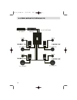
Page 12: ...ER HEAD UNIT PRE OUT FRONT REAR BASS MIDRANGE X OVER X OVER TWEETER X OVER X OVER BASS MIDRANGE TWEETER BASS MIDRANGE TWEETER BASS MIDRANGE TWEETER CHANNEL 1 CH CHANNEL 3 CH CHANNEL 2 CH CHANNEL 4 CH EA 2 4 CH Manual 12 03 2002 12 55 Uhr Seite 12 ...

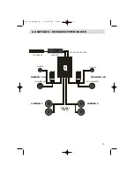
Page 13: ...ASS SYSTEM EA4150 CD CHANGER HEAD UNIT BASS MIDRANGE X OVER X OVER TWEETER BASS MIDRANGE TWEETER CHANNEL 1 CH CHANNEL 2 CH KICKBASS STEREO CHANNEL 3 CHANNEL 4 PRE OUT FRONT REAR EA 2 4 CH Manual 12 03 2002 12 55 Uhr Seite 13 ...

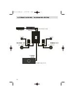
Page 14: ...E SUBWOOFER SYSTEM CD CHANGER HEAD UNIT BASS MIDRANGE X OVER X OVER TWEETER BASS MIDRANGE TWEETER CHANNEL 1 CH CHANNEL 2 CH CHANNEL 3 4 CH TRUNKBOX SUBWOOFER PRE OUT FRONT REAR EA 2 4 CH Manual 12 03 2002 12 55 Uhr Seite 14 ...

Page 15: ...eive filtered signals so the speakers will only have to work in the frequency bands they can reproduce best 7 2 SELECTING A CROSSOVER FREQUENCY POINT FOR SATELLITE SPEAKERS For satellite speakers you must select the position HP on the OPERATION MODE switch The HP operation mode will take away unnecessary mechanical and electrical strain from the connected coa xial or component speaker systems as t...

Page 16: ... Before you can attempt to find the sonically best lowpass crossover frequency point you must set the subsonic highpass filter control when BP mode is turned on to its lowest position 10Hz so it will not interfere with the lowpass crossover frequency adjustment Close the electrical circuit by inserting the main fuse Now switch on your head unit The green OPE RATING LED of the amplifier should ligh...

Page 17: ...inimum positions and start with the channel pair that drives the subwoofer system The REMOTE LOW PASS LEVEL BOOST if installed in your system configuration shall be set to its minimum position too SUBWOOFER CHANNELS Set the volume control of your head unit to approximately 3 4 of full volume while playing a dyna mic piece of music Slowly increase the input gain control of the channel pair that dri...

Page 18: ... locations separated by at least 2 5m of distance there is always a time or wave length difference between these two speaker systems A difference in phase bigger than 90 will cause a partial cancellation of the frequencies that are radiated at the specific crossover point Two effects derive from this fact 1 the sound reproduc tion is not as tight as it can be and 2 the subwoofer can easily be loca...

Page 19: ...n Möglichkeiten und technischen Features dieses Verstärkers vertraut zu machen Lesen Sie deshalb die nachfolgenden Abschnitte sorgfältig durch und bewahren Sie diese Bedienungsanleitung für allfällige vielleicht später auftauchende Fragen auf WICHTIGE INFO Wenn Sie den Einbau Ihres Car HiFi Systems selbst vornehmen lassen Sie dieses von Ihrem Händler auf fachgerechte Installation überprüfen Damit ...

Page 20: ...RUKTION Durch die ausschliessliche Verwendung von hochwertigsten Materialien in der Fertigung ist die Betriebssicherheit besonders hoch Zum Einsatz kommen z B doppelseitig kaschierte Glasfaser Epoxydharzplatinen hochstromfä hige Transistoren etc Weiterhin verfügt dieser Verstärker über 35mm2 Power Input Terminals für vol len unlimitierten Stromfluss sorgen INTELLIGENTE SCHUTZSCHALTUNG Die integrie...

Page 21: ...NDPASS BETRIEB DER KANÄLE 1 2 CH Druckschalter für Tiefpass oder Bandpass Betrieb der integrierten elektronischen Frequenzweiche der Kanäle 1 2 CH Dieser Schalter ist nur aktiv wenn der Operation Mode Schiebeschalter des betreffenden Kanal Paares auf LP BP steht siehe Abschnitt 7 3 7 4 7 5 8 REGLER EINGANGSEMPFINDLICHKEIT DER KANÄLE 3 4 CH Eingangsempfindlichkeitsregler der Kanäle 3 4 CH für die A...

Page 22: ...gseinheit siehe Abschnitt 6 1 16 POWER LED Grüne Power LED signalisiert den normalen Betriebszustand der Endstufe im eingeschalteten Zustand siehe auch Abschnitt 7 5 17 PROTECTION LED Rote Protection LED signalisiert eine generelle Fehlfunktion der Endstufe wie z B Kurzschluss an den Lautsprecherausgängen Überhitzung sowie Gleichspannung an den LS Ausgängen siehe Abschnitt 7 5 18 AUSGANGSBUCHSE Fe...

Page 23: ... siehe Abschnitt 6 3 21 GND POWER INPUT TERMINAL 35mm2 Eingansterminal für den Anschluss an die Chassis Masse des Kfz s oder den Minuspol der Fahrzeugbatterie siehe Abschnitt 6 3 22 REM INPUT TERMINAL Eingangsterminal für den Anschluss des Remote Kabels über den Amp oder Antenna Remote Ausgang des Steuergerätes siehe Abschnitt 6 1 23 LAUTSPRECHER AUSGANGS TERMINAL Lautsprecheranschlussterminal für...

Page 24: ...inbau dieser Komponente durch den autorisierten und geschulten Fachhandel 3 1 MONTAGEORT Der Verstärker muss im Interesse der passiven Sicherheit stabil befestigt werden Prüfen Sie ob die gewählte Montagefläche eben und stabil genug zur sicheren Befestigung des schweren Verstärkers ist Als Montageort eignet sich z B ein Platz im Kofferraum oder an einem Seitenteil bzw jeder andere Ort der eine sau...

Page 25: ... DER LAUTSPRECHER Die Wärmekapazität der Kühlrippen dieser Endstufe wurde für sehr niederohmige Lasten ausgelegt Unterstützend wirkt der innenliegende Lüfter der im Normalfall das Überhitzen dieses Verstärkers ver hindert Die Kühlkapazität ermöglicht den normalen Betrieb an 1 Ohm Lasten in stereo Konfiguration oder 2 Ohm mono im Brückenbetrieb BRIDGED Noch tiefere Lastimpedanzen sind nicht empfeh ...

Page 26: ...ine Zange für das Abisolieren der Kabel Entfernen Sie ca 6 8 mm der Isolierung des LS Kabels und beachten Sie die richtige Polung der Lautsprecherkabel am Terminal Plus auf Plus Minus auf Minus Ziehen Sie die LS Schraublemmen satt an 6 3 VERLEGEN UND ANSCHLUSS DER HAUPT STROMKABEL Verlegen Sie nun das Pluskabel direkt von der Batterie zum Verstärker Wir empfehlen die Verwendung von massiven Batter...

Page 27: ...P basierte Weiche an Ihrem Steuergerät falls vorhanden oder die Weichenfunktionen an der Endstufe Ein Betrieb von Kompo oder Koaxialsystemen ohne aktivierte Hochpass Weiche kann die angeschlossenen Lautsprecher zer stören 7 2 WAHL DER TRENNFREQUENZ FÜR DIE SATELLITENSYSTEME Mit der Einstellung der Trennfrequenz des Hochpasses HP soll eine elektrische und mechanische Entlastung der verwendeten Koax...

Page 28: ...folgt wieder rein gehörmässig daher müssen Sie den GAIN Regler von Kanal 5 6CH auf ca 12 Uhr Stellung bringen und Ihr Steuergerät einschalten um eine passende Trennfrequenz festzulegen Eine zu tiefe Trennfrequenz lässt den Bassbereich kraftlos und unkonturiert wirken Eine zu hohe Trennfrequenz bewirkt ein Dröhnen des Bassbereichs Die passende Tiefpass Trennfrequenz ist übrigens stark abhängig vom ...

Page 29: ...h ein ausgewogener basskräftiger Klang einstellt Nun können Sie noch in einem letzten Step wenn vorhanden den GAIN Regler von weiteren Kanälen entsprechend aufdrehen z B um das Hecksystem einzupegeln oder um ein Kickbass System in der Lautstärke anzupassen Meist ist am Schluss nochmals ein Feinabgleich aller Eingangsempfindlichkeits Regler fällig und im gleichen Zug empfiehlt es sich auch die Tren...

Page 30: ... 8V THD 0 1 All channels driven simultaneously 1200Wx1 Bridged 505Wx2 Bridged Damping Factor All Channels stereo 4Ohms 100Hz 200 Signal to Noise Ratio All channels 93 dB Frequency Response all channels frequency filtering controls deactivated 10Hz 50 kHz 0 dB 1 dB Channel Separation 60 dB all channels Input Sensitivity all channels 200 mV 9 4V Integrated Active Filtering Slope Rates 12 dB octave C...

Page 31: ...Kunde sehr geehrte Kundin Wir bitten Sie die Originalverpackung für einen allfälligen Transport aufzuheben und die untenstehenden Garantie Bestimmungen genau durchzulesen Sollten Sie für Ihren Verstärker Garantie Leistungen beanspruchen wenden Sie sich bitte direkt an den Händler bei dem Sie das Gerät gekauft haben Bitte senden Sie keine Geräte an EMPHASER Inc U S A Bei Schwierigkeiten ein geeigne...

Page 32: ...Postal Code Country Your phone number Limited Warranty 24 Months Valid with authorized Installation Approval only Dealer s address stamp Installed by authorized dealer Installation date Inspected and approved by Installation Approval Self installed by customer EMPHASER Inc Wyoming Michigan U S A EA 2 4 CH Manual 12 03 2002 12 55 Uhr Seite 32 ...

Reviews: