background image

2

HWW HWN  HWe  HWs

Fp9

Fp12

Fp3

Fp6

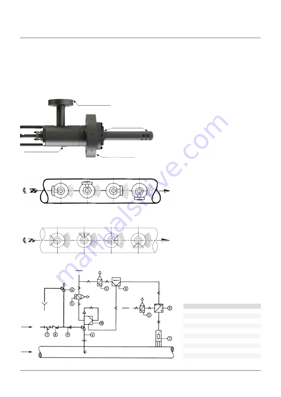
FIgure 4

FIgure 3

Water flange positions

steam line

steam flow

Handwheel positions

steam line

steam flow

air

air

Water

steam

YArwAY

 TemplowHT desuperHeaTer

InstallatIon and MaIntenance InstructIons

The minimum pipe run, required downstream 
of the TemplowHT desuperheater, varies 
with each individual application and would 
be specified by Yarway at the enquiry stage. 
This straight run is needed to prevent erosion 
due to impingement of water droplets against 
pipewalls, valves and fittings and is normally 

item

Description

1

Temperature sensor

2

Temperature transmitter

3

Temperature controller

4

TemplowHT desuperheater

5

air filter regulator

6

safety relief valve

7

strainer

8

Check valve

9

Flange

10

e/p-positioner

FIgure 1 - Model 59/69/79

Check for damages

Identification plate

Check for damages

Check for damages

in the order of 4 to 6 meters, as a minimum (no 
upstream straight length is normally required).
The distance from the TemplowHT desuperheater 
to the temperature sensor is nominally 12 to 
15 meters, although the distance specific to 
the application would be advised by Yarway at 
the enquiry stage. longer distances will ensure 

that full evaporation of the water will take place 
at lower steam velocities.
The temperature sensor should be located in 
the upper half of the pipe, avoid branching of 
the steam pipework between the TemplowHT 
desuperheater and the sensor (see figure 4).

Summary of Contents for Yarway TempLowHT

Page 1: ...connection yoke actuator or any of its accessories for lifting Leave the flange covers in place during transportation until ready to install in the pipework Warning The hoisting lug is for the actuator only NOT for a total assembly When installing the TempLowHT Desuperheater use gaskets and bolting material in accordance with the relevant piping code for example ASME B31 1 or AD 2000 EN Place the ...

Page 2: ...rature controller 4 TempLowHT Desuperheater 5 Air filter regulator 6 Safety relief valve 7 Strainer 8 Check valve 9 Flange 10 E P positioner Figure 1 Model 59 69 79 Check for damages Identification plate Check for damages Check for damages in the order of 4 to 6 meters as a minimum no upstream straight length is normally required The distance from the TempLowHT Desuperheater to the temperature sen...

Page 3: ...er droplets in suspension until complete evaporation has taken place Installation may be in vertical or horizontal piping but the direction of water injection should always be with the steam flow The TempLowHT Desuperheater may be mounted at 90 to the steam pipe for all steam flow orientations but avoid installation in the vertically downwards position wherever possible see figure 5 Yarway supplie...

Page 4: ... can remain in situ If damaged use a pipe wrench and unscrew the seat counterclockwise Discard of metallic seal ring 19 This ring cannot be re used Maintenance Note Maintenance of the TempLowHT Desuperheater is straight forward and does not require any special tools or training Care should be taken during any maintenance operation particularly when working with grinders compressed air and rotating...

Page 5: ... dress with a fine file Nozzles 17 may be replaceable If this is wanted check with Yarway for possibilities as special PWHT may be required at this operation Stem 6 Withdraw the piston stem The piston and stem are always supplied as a complete assembly If the piston shows no signs of wear and tear then it may be re used Replace piston rings as a matter of course any time that the unit is disassemb...

Page 6: ...ing during installation is very important for the tightness of the seal Do not use screwdriver or other sharp object to seal the packing This could damage the packing and or stem If a packing driver is used make sure that the diametrical clearances between the I D of the driver and O D of the stem and the O D of the driver and I D of the stuffing box do not exceed 0 5 mm 0 020 6 Stagger the joints...

Page 7: ...e spray with the direction of the steam flow Apply a high temperature lubricating compound to the bolts and nuts and tighten evenly in accordance with the manufacturer s recommendations Before connecting the water line flush through and check for any contamination or restriction in the supply Spare parts Make sure that the identification number indicated on the nameplate is verified and specified ...

Page 8: ... 17 Cr 3 1 Control cylinder assembly AISI 431 4 1 Seal SS graphite 5 1 Gasket SS graphite 6 1 Stem incl piston AISI 431 nitrited 7 1 Injection probe A182 F91 F22 8 1 Pin spray cylinder AISI 304 9 1 Packing set Graphite 10 1 Gland packing AISI 304 11 1 Bushing spacer AISI 431 nitrited 12 1 Bushing gland AISI 431 nitrited 13 4 Stud packing gland A193 B16 14 4 Nut packing gland A194 4H 15 16 Stud inj...

Page 9: ...6 8 Nut injection probe A194 4H 17 Nozzle Inconel 718 18 1 Name plate AISI 304 19 1 Seal ring SS graphite 20 1 Lock nut C Steel 21 1 Coupling C Steel 22 1 Water flange A182 F91 F22 23 1 Yoke C steel 24 3 Piston ring AISI 431 nitrited 25 1 Actuator 26 1 Positioner 27 1 Air filter regulator Figure 11 model 69 79 Notes See certified drawing Recommended spare part Materials and data of units supplied ...

Page 10: ...son logo are trademarks and service marks of Emerson Electric Co All other marks are the property of their respective owners The contents of this publication are presented for informational purposes only and while every effort has been made to ensure their accuracy they are not to be construed as warranties or guarantees express or implied regarding the products or services described herein or the...

Reviews: