


3
INSTALLATION
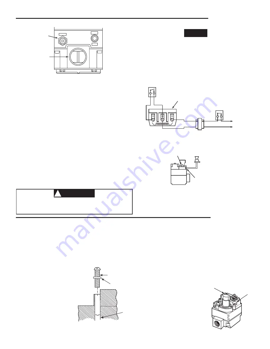
Pilot Gas
Outlet
Gas Outlet
PRESS
TAP
PILOT
Figure 3. Gas valve side view
THERMOCOUPLE CONNECTION
The thermocouple connection should be clean to ensure good
electrical contact.
Run the thermocouple nut into the power unit tapping as far as pos-
sible by hand. Then use a small wrench to set the nut with a
1
⁄
4
to
1
⁄
2
additional turn.
Do not overtighten
.
Connect leads from E.C.O. terminals to E.C.O. device on furnace.
Test E.C.O. device for continuity. If there is no continuity, power unit
will not hold in.
If the furnace does not have an E.C.O. device, use the jumper pro-
vided in the pack.
SYSTEM WIRING
CAUTION
!
To prevent electrical shock and/or equipment damage,
disconnect electrical power to system at main fuse or circuit
breaker box until installation is complete.
ENERGY CUT OFF (E.C.O.) CONNECTION
A five-function valve uses the 2 E.C.O. terminals that are connected
to the magnetic assembly where the thermocouple connects to the
36C valve line interrupter. An E.C.O. device is mounted in the furnace
near the limit control and a lead assembly is connected to the E.C.O.
terminals on the 36C valve.
THERMOCOUPLE
CONNECTION
E.C.O.
DEVICE
LEAD
ASSEMBLY
E.C.O. TERMINALS
Figure 5. Wiring for Energy Cut-Off (E.C.O.) connection
NOTE
All wiring should be installed in accordance with local and
national electrical codes and ordinances.
Always check that the electrical power supply used agrees with the
voltage and frequency shown on the gas control.
The typical wiring diagram shows only the terminal identification
and wiring hook up. Always refer to wiring instructions provided
by
Equipment Manufacturer for system hookup operation.
PRESSURE REGULATOR ADJUSTMENT
The pressure regulator has been factory adjusted (see control
for specific setting). Although additional adjustments will not
normally be necessary, you may adjust the regulator.
Do not
force the adjusting screw beyond the limits that it can
easily be adjusted.
1. Energize valve to ignite main burner.
2. Remove "Reg. Adj." cover screw (see fig. 7).
3.
To DECREASE outlet pressure
, turn the adjusting
screw (beneath the
cover screw) counter-
clockwise.
To IN-
CREASE outlet pres-
sure
, turn the adjust-
ing screw clockwise.
4. Replace the cover
screw. Cycle the valve
two or three times to
verify regulator setting.
Pilot Adjust
Cover Screw
Gasket
Pilot
Adjust
Screw
Figure 6. Pilot Flame Adjustment
OFF
PI
LO
T
ON
PILOT ADJUST
COVER SCREW
Figure 7. Pressure regulator adjustment
REGULATOR ADJUSTING
COVER SCREW
PILOT FLAME ADJUSTMENT
If the pilot flame is low and does not engulf the bulb of the
mercury flame sensor, the system will not energize the main
valve. If pilot gas pressure is too high, gas will sputter past the
ignition electrode, and may not ignite. High pilot gas pressure
may also cause the flame to lift off the burner, causing the
flame sensor bulb to sense "low" heat.
To adjust the pilot gas pres-
sure, remove the cover screw
(see fig. 6).
To REDUCE
pilot pressure
, turn the pilot
adjust screw (beneath the
cover screw) clockwise.
To
INCREASE pilot pressure
,
turn the pilot adjust screw
counterclockwise. Replace
and tighten cover screw.
ADJUSTMENT
GAS VALVE
TERMINAL PANEL
Figure 4. Wiring for 36C53
TH TH-TR
TR
LINE
HIGH
LIMIT
24 VAC
HOT
TRANSFORMER
THERMOSTAT
Figure 3. Gas valve side view
Figure 4. Wiring for 36C53
Figure 5. Wiring for Energy Cur-Off (E.C.O.) connection
Figure 6. Pilot flame adjustment
Figure 7. Pressure regulator adjustment