background image

Mechanical Installation

20

Installation, Operation, and Maintenance Manual

ES-09373-1


  Mechanical Installation

  August 17, 2022


5.4 

Linear Actuator Installation (Continued)

5.4.6 

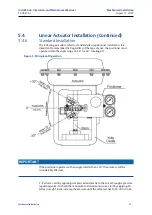
Standard Installation

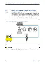
1 - Perform a test by applying compressed air directly to the valve through a pressure 
regulating valve. To check the maximum and minimum stroke, start by applying 0% 
(valve closed). Slowly increase the pressure until the valve reaches 100% of its stroke.

For the positioner assembly, it is recommended to release the air through the 
regulator so that the valve reaches 50% of its full stroke.

Caution when handling compressed air hoses, make sure the line is disconnected 
before connecting it to the positioner.

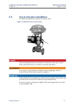
Figure 5-19 Testing the Positioner’s Travel and Mounting Position

         CAUTION

Summary of Contents for TopWorx PD100

Page 1: ...Installation Operation and Maintenance Manual ES 09373 1 August 17 2022 Emerson TopWorx TM PD100 Smart Valve Positioner ...

Page 2: ...ction installation use maintenance and repair Do not use the positioner outside the operating range as it may cause failures or even accidents with serious injuries See Section 2 Specifications For installation in a potentially explosive atmosphere make sure you have the positioner correctly specified for this purpose Products for explosion hazard areas have the EN or ES suffix at the end of the c...

Page 3: ...y This symbol in combination with the signal word WARNING indicates a possibly dangerous situation Failure to observe the safety warning can cause death or very serious injury CAUTION Risk of injury This symbol in combination with the signal word CAUTION indicates a possibly dan gerous situation Failure to observe the safety warning can cause injury WARNING Material Damage This symbol in combinati...

Page 4: ...Rotary NAMUR Bracket to the Actuator 12 5 4 Linear Actuator Installation 15 5 4 1 Assembling the Guide Arm 16 5 4 2 Installing the Feedback Lever and Bracket 16 5 4 3 Yoke Castle Mount 17 5 4 4 Mounting on a Pillar Type Castle 17 5 4 5 Types of Feedback Lever 18 5 4 6 Standard Installation 19 Section 6 Pneumatic Connections 24 6 1 Manifold Types 25 6 2 Pneumatic Connection on Rotary Actuator 26 6 ...

Page 5: ...tallation Operation and Maintenance Manual ES 09373 1 Table of Contents August 17 2022 Contents Section 9 Certifications 45 Section 10 Mechanical Dimensions 46 10 1 Rotary Positioner Dimensions 46 Section 11 How to Specify 47 ...

Page 6: ...aining or have general knowledge in the field Knowledge and technical application of the safety instructions and warnings in this manual are of utmost importance for risk free mounting and commissioning This will ensure safety during operation and maintenance of the product This manual is not an integral part of the delivery of the positioner and is subject to change without notice The manual is a...

Page 7: ...n of Liability This manual contains the most relevant information for the positioner to be mounted and configured correctly It is the responsibility of the technician to know the safety regulations and practices applicable in your country It is also your responsibility to read and understand the information described here In case of questions the technician must contact our application engineering...

Page 8: ...VDC external power supply Impedance Output 800 Ω 20mA 24 VDC Linearity 0 8 of Full Scale Hysteresis 1 5 of Full Scale Repeatability 1 45 of Full Scale Minimum Step Response 0 3125 Full Scale or 50 µA Start up 8 seconds Insulation Resistance 25 G ohms Approved in dielectric resistance test 500 VDC Lifetime 150 K cycles Operating Temperature Limits 40 C 40 F LCD may not be readable below 20 C 4 F 80...

Page 9: ...utput 311 l min 17 7 N m3 h 11 scfm 660 scfh considering the pressure of 60 psi 4 1 bar Valve Flow Characteristics Linear Equal Percent age fast Opening Pneumatic Connections Supply and Output Pressure NPT Female Conduit Connections NPT Female Housing and Cover Material FARADEX Display window Polycarbonate Module Base Assembly Aluminum Manifold ZAMAK 5 Elastomers Nitrile NBR Protection class IP66 ...

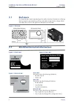
Page 10: ...the mechanical configuration buttons and electrical terminals you must remove the product cover Figure 3 1 Overview Item Description 1 Four Digit LCD display 2 Plate Cover 3 Manifold with Pressure Gauges 4 Mechanical UP Button 5 Mechanical ENTER Button 6 Mechanical DOWN button 7 Air Exhaust 8 Electrical Terminals Control and Feedback Signals 9 Cable Entry ...

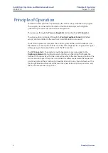
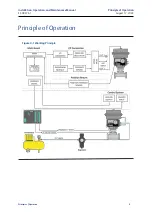
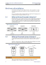
Page 11: ...e the ignition of the explosive atmosphere 3 2 Identification Label Information Figure 3 1 Enclosure Figure 3 2 Front Label Figure 3 3 Side Label Figure 3 4 Internal Label Front Label This label contains the following information Manufacturer ID Order code Side Label This label carries the following information Model number Serial Number Operation Information Internal Label This label contains the...

Page 12: ...product Make sure that the contents are undamaged and that they are in accordance with the scope of delivery and as described on the invoice If there are any discrepancies please contact us immediately The positioner is supplied in a closed package containing the following items Intelligent electropneumatic positioner Linear or rotary actuator adaptor as specified ...

Page 13: ...rocessor The fast microprocessor compares the control signal and the position feedback and the difference is the input to the PID controller that will generate an appropriate signal in frequency to be applied to the coil of the I P converter The I P Converter is the nozzle vane that generates a pressure signal to the Diaphragm Module that will create a dynamic force on the spring that breaks the b...

Page 14: ...9 Principle of Operation Installation Operation and Maintenance Manual ES 09373 1 Principle of Operation August 17 2022 Principle of Operation Figure 4 1 Working Principle ...

Page 15: ...nical motion These devices can be single acting where they receive air to open or close the valve and return to their original position by means of a spring without the need for air or double acting which requires compressed air to move in both directions 5 2 What are Pneumatic Linear Actuators Linear pneumatic actuators are devices that convert the stored energy of compressed air into a linear me...

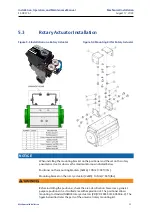
Page 16: ...e set on the rotary pneumatic actuator observe the maximum torque indicated below Positioner on the mounting brackets 4xM6 10 Nm 7 38 ft lbs Mounting bracket on the rotary actuator 4xM5 10 Nm 7 38 ft lbs Before installing the positioner check the area classification Never use a general purpose positioner in a classified area with explosion risk The positioner allows mounting to standard NAMUR rota...

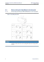
Page 17: ...09373 1 Mechanical Installation August 17 2022 5 3 Rotary Actuator Installation Continued 5 3 1 Mounting the Rotary NAMUR Bracket to the Actuator Check the L and H position for correct mounting of the positioner to the pneumatic actuator Figure 5 5 Assembling the Bracket NOTICE ...

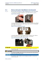
Page 18: ...the Rotary Support to the Actuator 3 Mount the bracket to the positioner by placing the four M6x10 screws with lock washers and plain washers Tighten the screws with a 10 mm wrench The positioner can be installed at any starting angle and operates in any position vertical or horizontal Be careful when handling compressed air hoses make sure the line is disconnected before connecting it to the posi...

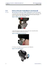
Page 19: ...ngaging the positioner end cap on the shaft of the rotary actuator attach the four M5x10 screws with lock washers and plain washers Tighten the screws with an 8 mm wrench 5 Make the pneumatic and electrical connections See Section 6 Pneumatic Connections and item 7 Electrical Connections 6 Perform a fast calibration See Section 8 3 Fast Calibration Figure 5 9 Fitting on the Actuator Shaft Figure 5...

Page 20: ...oner check the area classification Never use a General Purpose positioner in an area classified as an explosive atmosphere Excess pressure can permanently damage the actuator diaphragm Check the actuator manual for the maximum pressure supported IMPORTANT When installing the mounting bracket on the positioner and then setting on the linear pneumatic actuator observe the maximum torque indicated be...

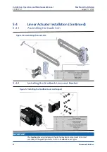
Page 21: ...tor Installation Continued 5 4 1 Assembling the Guide Arm 5 4 2 Installing the Feedback Lever and Bracket Figure 5 6 Assembling the Guide Arm Figure 5 7 Installing the Feedback Lever and Support IMPORTANT The feedback lever is graduated Check the maximum valve travel for correct assembly of the guide pin Refer to 5 2 6 Feedback Lever Types ...

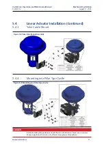
Page 22: ... Actuator Installation Continued 5 4 3 Yoke Castle Mount 5 4 4 Mounting on a Pillar Type Castle Before installing the positioner check the area classification Never use a General Purpose positioner in an area classified as an explosive atmosphere Figure 5 8 Yoke Type Bonnet Assembly Figure 5 9 Mounting on a Pillar Type Castle DANGER ...

Page 23: ...tinued 5 4 5 Types of Feedback Lever The feedback levers are classified by two stroke lengths K3 and K4 which are di rectly linked to the minimum and maximum operating stroke Check the maximum valve travel to use the correct feedback lever For mounting the lever see 5 4 2 Installing the Feedback Lever and Bracket Figure 5 10 Types of Feedback Levers IMPORTANT ...

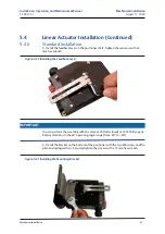
Page 24: ...hat regardless of the type of yoke the positioner must operate within the angle range of 30 to 30 totaling 60 If the positioner operates with an angle smaller than 30 the accuracy will be considerably affected 1 Perform a test by applying compressed air directly to the valve through a pressure regulating valve To check the maximum and minimum stroke start by applying 0 valve closed Slowly increase...

Page 25: ...ulating valve To check the maximum and minimum stroke start by applying 0 valve closed Slowly increase the pressure until the valve reaches 100 of its stroke For the positioner assembly it is recommended to release the air through the regulator so that the valve reaches 50 of its full stroke Caution when handling compressed air hoses make sure the line is disconnected before connecting it to the p...

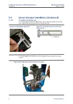
Page 26: ...t Tighten the setscrew with a 5 mm hex wrench You can perform the assembly with the valve at 0 fully closed or 100 fully open but pay attention to the 60 operating angle range from 30 to 30 3 Install the bracket on the bottom of the positioner with the two M8 screws and the plain and spring washers Securely tighten the screws with a 13 mm hex wrench IMPORTANT Figure 5 20 Installing the Feedback Le...

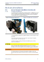
Page 27: ...stallation 4 Install the guide pin in the feedback lever observing the maximum travel of the valve Tighten the retaining nut with a 10 mm hex wrench 5 Install the guide arm on the valve stem Tighten the screws with a 10 mm hex wrench Figure 5 22 Installing the Dowel Pin Figure 5 23 Guide Pin in the Correct Position Valve Travel Figure 5 24 Installing the Guide Arm on the Valve Stem ...

Page 28: ...ten the bracket screws firmly with a 13 mm hex wrench 8 Make the pneumatic and electrical connections See Sections 6 Pneumatic Connections and 7 Electrical Connections 9 With all connections made perform the auto calibration process See the item 8 3 Fast Calibration Risk of crushing and shearing with mounting kits that use a lever for position detection During commissioning and continuous operatio...

Page 29: ...r can partially or completely damage the positioner s internal components Before connecting the conduit it is essential to remove dust oil or other impurities Before instrumentation air is connected to the positioner we recommend that the hose be opened freely for 2 to 3 minutes to allow any contamination to escape A pressure exceeding 10 bar 145 psi may permanently damage the positioner Measures ...

Page 30: ...ssure is 2 8 to 8 bar 40 to 116 psi but the actuator may operate with a different pressure Unused outputs must be plugged Refer to 6 2 and 6 3 We recommend installing a pressure regulating filter between the pneumatic line and the positioner s pressure inlet connection High pressures may damage both the positioner and the valve actuator 6 1 Manifold Types The PD100 positioner is supplied with one ...

Page 31: ... Rotary Actuator Check below the pneumatic connection for each type of rotary actuator 6 3 Pneumatic Connection on Linear Actuator Check below the pneumatic connection for each type of linear actuator The unused outlet must be capped IMPORTANT Table 6 2 Pneumatic Connections on Rotary Actuators Table 6 3 Pneumatic Connections in Linear Actuators ...

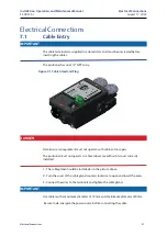
Page 32: ... operate with cable entries open The positioner must not operate in a hazardous area without its cover correctly installed 1 The cable gland should be installed as in the picture above 2 Turn the cover of the cable gland counterclockwise to open and insert the wires 3 Connect the wires to the terminals and tighten the cable gland Use cables with a maximum diameter of 12 mm and a minimum diameter o...

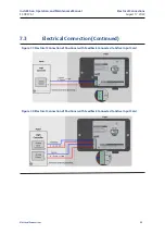
Page 33: ...ith screw terminals intended for connection of the control signal and feedback signal Be sure to supply the rated voltage and current indicated in this manual see Section 2 Technical Specifications Failure to do so may cause serious damage or malfunctioning of the positioner Despite the polarity indications reversing them does not alter the positioner s operation When it is necessary to open the p...

Page 34: ...al ES 09373 1 Electrical Connections August 17 2022 7 3 Electrical Connection Continued Figure 7 3 Electrical Connection of Positioner with Feedback Connected to Active Input Card Figure 7 4 Electrical Connection of Positioner with Feedback Connected to Active Input Card ...

Page 35: ...Configuration Buttons The PD100 positioner has three mechanical buttons for configuration To configure the positioner you must open the cover by removing the four screws which fasten it to the positioner housing Figure 8 1 Positioner with Cover Figure 8 2 Positioner without Cover Figure 8 3 Position of Mechanical Buttons ...

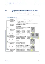
Page 36: ...guration August 17 2022 8 2 Entering and Navigating the Configuration Menu To enter and navigate the configuration menu via the mechanical buttons you must remove the cover See below how to enter and navigate in the configuration menu of the positioner Figure 8 4 Entering the Menu ...

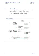
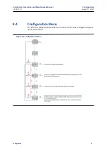
Page 37: ... calibration the positioner performs a complete calibration obtaining all valve parameters For example the opening and closing positions and the PID values To perform a fast calibration follow the steps below 1 Press the DOWN button until Sure appears in the display 2 Use the ENTER button to confirm the calibration Figure 8 5 Fast Calibration ...

Page 38: ...n Operation and Maintenance Manual ES 09373 1 Configuration August 17 2022 8 4 Configuration Menu The PD100 s configuration menu has four functions that can be configured using the mechanical buttons Figure 8 6 Configuration Menu ...

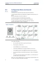
Page 39: ...ameters Kp Tr and Td NOTE Recommended use in a process changeover Accessing the Setup Menu Press the ENTER button for 3 seconds to enter the menu The first option is the SET menu Use the ENTER button to select this function Use the UP or DOWN buttons to navigate to the item you wish to set Use the ENTER button for the calibration procedure you want to perform To continue with the selected calibrat...

Page 40: ...rol P Proportional and integral control PI Proportional and derivative control PD Proportional Integral and Derivative control PID Proportional Control Proportional control always works on top of the system error that is it will generate an output according to the error and not as a function of time The gain Kp is the variable that the proportional controller uses for control A value that is too l...

Page 41: ...ow and inefficient integration Derivative Control The derivative action like the integral action works with time Td and is also used in conjunction with the proportional action PD control This control is very efficient with respect to correction because it starts the correction immediately as soon as the error starts as the derivation of constant is always zero As in PI control this control also s...

Page 42: ...tegral time Tr and derivative time Td manually To this end there are a few methods for adjusting the parameters tuning Borderline Sensitivity Method This method will work on the closed loop setting It will first reduce the effect of the integral and derivative actions to a minimum Only then will it start with the gain Kp and increase it until the controlled variable oscillates with the amplitude t...

Page 43: ...hen the plant model is unknown A few rules for PID tuning are presented These rules are based on his experiments which works on steps and gain They provide an estimate of the parameters of integral time derivative time and proportional gain Sometimes this signal can generate a very large step response In that case you will need to do some finer tuning to get the desired adjustment Auto Tuning Meth...

Page 44: ...se the UP or DOWN buttons to select an option Press ENTER button to select the option Use the UP or DOWN buttons to increase or decrease the value Hold down to increase or decrease rapidly When the value is ready store it with the ENTER button and return to the KP Td and Tr setting to set the other if desired If you enter KP Tr or Td and want to exit wait 30 seconds without pressing any buttons an...

Page 45: ...elow Accessing the CRT Menu Press ENTER button for 3 seconds to enter the menu Use the DOWN button to move to the CTR option The UP button returns to the previous option Use the ENTER button to select the option Set the control signal to 4 mA then confirm the 4 mA point with the ENTER button Set the control signal to 20 mA then confirm the 20 mA point also with the ENTER button If you wish to exit...

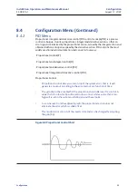
Page 46: ...er into operation To test the signal connect a 4 to 20 mA current generator to the H and H terminals Connect a 24 V DC voltage source in series with a current rated multimeter to terminals RT and RT Set the current generator to 4 mA and gradually increase by checking the output signal feedback on the multimeter See the graph below for 4 to 20 mA current values The output signal must be the same as...

Page 47: ...he T OUT Menu Press ENTER button for 3 seconds to enter the menu Use the DOWN button to move to the T OUT option The UP button returns to the previous option Use the ENTER button to select the option The display shows SURE To continue use the ENTER button Use the ENTER button to select the digit and the UP or DOWN buttons to change the digit When the value is ready confirm with the ENTER button fo...

Page 48: ...d for the actuator to go to position A example Open and after 10 seconds it accumulates internal fault 2 since there was no movement C Then the display shows 10 and the positioner sends a new command for the actuator to move to position B example Closed D Tout Alert is triggered generating an initial lack of movement fault Note that only after internal faults 1 2 and 3 is the Tout Alert generated ...

Page 49: ...nd the positioner sends a new command for the actuator to go to position B example Open action successfully accomplished within 10 seconds D The display changes to 15 and the positioner sends a new command for the actuator to go to position A example Open and after the 10 seconds elapsed internal fault 1 occurs because there was no movement E Then the display changes to 20 and the positioner sends...

Page 50: ...2 BURST Fast Transients According to IEC 61326 1 and IEC 61326 2 3 Table 2 acceptance criteria B IEC 61000 4 8 and IEC 61514 2 clause 5 5 2 Magnetic Fields IEC 61000 4 2 e IEC 61514 2 ítem 5 5 2 Electrostatic Discharge IEC 61000 4 6 Immunity to conducted disturbances induced by radio frequency fields IEC 61000 4 5 Surge Immunity Test PD100 input 4 to 20mA 1 kV Line to Ground Feedback 4 to 20 mA 1k...

Page 51: ... Dimensions 10 1 Rotary Positioner Dimensions Figure 10 1 Rotary Positioner Figure 10 2 Linear Positioner Mounting Torque Positioner in the mounting bracket 4xM6 10 Nm Mounting bracket on the rotary actuator 4XM5 10 Nm Mounting Torque Positioner in the mounting bracket 2xM8 15 Nm Mounting bracket on the rotary actuator 2XM8 15 Nm ...

Page 52: ... Example PD100 C F N G RN Model PD100 Smart Valve Positioner with standard controls Input Communication C 4 20mA Feedback Output F Isolated position feedback transmitter 4 20mA Electric and Pneumatic Connections N Single conduit entry 1 2 NPT Pneumatic manifold with 1 4 NPT Pneumatic Manifold G ZAMAC Manifold with two pressure gauges Type of Actuator Adaptor RN Rotary NAMUR adaptor K3 Linear feedb...

Page 53: ...Estate Stockport SK6 2SU UK 44 0161 406 5155 info topworx emerson com 2013 2022 TopWorx All rights reserved TopWorx and GO Switch are all trademarks of TopWorx The Emerson logo is a trademark and a service mark of Emerson Electric Co 2013 2022 Emerson Electric Company All other marks are the property of their respective owners Information herein including product specifications is subject to chang...

Reviews: