Functional Description
RTM-ATCA-F140 Installation and Use (6806800M97A
)
42
4.4.5
BCM8727 Status
The PCMULK, PCDRLK, PLOSB and LASI signals from each BCM8727 port are connected to the
RTM FPGA to allow them to be monitored by software. The PLOSB and LASI signals can also
generate an interrupt to the front-blade. Refer to
for further
details.
4.4.6
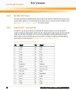
SFP+ Connection
The SFP+ cage accepts industry standard SFP+ optical modules. The SFP+ cage is backwards
compatible with 1 GB optical or copper SFP modules. Refer to the ATCA-F140 Installation and
Use Manual for a list of SFP devices tested with this product. The SFP+ connector assignment
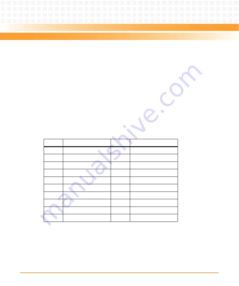
for the 10 Gbps serial interface is described in
4.4.6.1
I2C Bus
The SFP+ I2C bus signals (I2C_SDA and I2C_SCL) from each SFP+ site are individually
connected to the corresponding BCM8727 which includes a mechanism to allow access to the
port through the phy management channel.
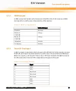
Table 4-6 SFP+ Connector Pin Assignment
Pin
Signal
Pin
Signal
1
GND
11
GND
2
TX_FAULT
12
RX-
3
TX_DISABLE
13
RX+
4
I2C_SDA
14
GND
5
I2C_SCL
15
VCCr (+3.3 V)
6
MOD_ABS
16
VCCt (+3.3 V)
7
RS0
17
GND
8
LOS
18
TX+
9
RS1
19
TX-
10
GND
20
GND
EA Version
Summary of Contents for RTM-ATCA-F140
Page 6: ...RTM ATCA F140 Installation and Use 6806800M97A Contents 6 Contents Contents EA Version ...
Page 8: ...RTM ATCA F140 Installation and Use 6806800M97A 8 List of Tables EA Version ...
Page 10: ...RTM ATCA F140 Installation and Use 6806800M97A 10 List of Figures EA Version ...
Page 20: ...Introduction RTM ATCA F140 Installation and Use 6806800M97A 20 EA Version ...
Page 34: ...Controls LEDs and Connectors RTM ATCA F140 Installation and Use 6806800M97A 34 EA Version ...
Page 58: ...Functional Description RTM ATCA F140 Installation and Use 6806800M97A 58 EA Version ...
Page 60: ...Related Documentation RTM ATCA F140 Installation and Use 6806800M97A 60 EA Version ...
Page 70: ...Index RTM ATCA F140 Installation and Use 6806800M97A 70 EA Version ...
Page 71: ...EA Version ...

