


Reference Manual
00809-0100-4882, Rev AB
May 2019
Rosemount 5081FG
Section 3
Startup and Operation
General . . . . . . . . . . . . . . . . . . . . . . . . . . . . . . . . . . . . . . . . page 3-1
Power Up . . . . . . . . . . . . . . . . . . . . . . . . . . . . . . . . . . . . . . . page 3-1
Establishing Proper Calibration Gas Flow Rate . . . . . . . page 3-3
Operation . . . . . . . . . . . . . . . . . . . . . . . . . . . . . . . . . . . . . . . page 3-4
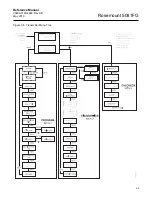
Program Menu . . . . . . . . . . . . . . . . . . . . . . . . . . . . . . . . . . . page 3-7
Diagnostics Menu . . . . . . . . . . . . . . . . . . . . . . . . . . . . . . . . page 3-16
Cal Check Menu . . . . . . . . . . . . . . . . . . . . . . . . . . . . . . . . . page 3-21
GENERAL
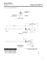
Verify Mechanical Installation
Ensure the Two-Wire In-Situ Oxygen Analyzer is installed correctly. See
Mechanical Installation in Section 2: Installation for mechanical installation
information.
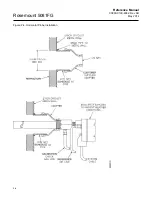
Verify Terminal Block Wiring
Ensure the wiring of both the oxygen probe terminal block and Rosemount
5081 transmitter terminal block is correct. Refer to Electrical Installation in
Section 2: Installation for electrical installation and wiring information.
POWER UP
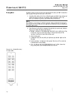
General
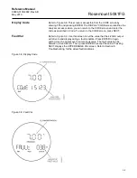
The Two-Wire In-Situ Oxygen Analyzer displays the current oxygen reading
on the LCD face of the Rosemount 5081 transmitter. The O
2
concentration,
cell temperature, and 4-20 mA output current are displayed as shown in
Figure 3-1. This and other information may also be accessed using
HART/AMS.
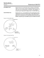
Startup Display
When the probe is first inserted into the stack, some time is required until the
minimum operating temperature [550°C (1022°F)] is reached. Some time is
also required for the electronics to reach an operating state. Therefore, when
the unit is first powered up, a faulted operation display as shown in Figure 3-2
may be displayed by the transmitter until the probe operating temperature is
reached and the electronics are working properly (approximately 5 minutes).
Install all protective equipment covers and safety ground leads before equipment startup.
Failure to install covers and ground leads could result in serious injury or death.
Summary of Contents for Rosemount 5081FG
Page 2: ......
Page 6: ...Reference Manual 00809 0100 4882 Rev AB June 2019 Rosemount 5081FG TOC 4 ...
Page 20: ...Reference Manual 00809 0100 4882 Rev AB May 2019 Rosemount 5081FG 1 10 ...
Page 36: ...Reference Manual 00809 0100 4882 Rev AB May 2019 Rosemount 5081FG 2 16 ...
Page 53: ...Reference Manual 00809 0100 4882 Rev AB May 2019 Rosemount 5081FG 3 17 Figure 3 20 Show Fault ...
Page 82: ...Reference Manual 00809 0100 4882 Rev AB May 2019 Rosemount 5081FG 6 6 ...
Page 94: ...Reference Manual 00809 0100 4882 Rev AB May 2019 Rosemount 5081FG A 8 ...
Page 96: ...Reference Manual 00809 0100 4882 Rev AB June 2019 Rosemount 5081FG B 2 ...
Page 98: ...Reference Manual 00809 0100 4882 Rev AB June 2019 Rosemount 5081FG B 2 ...
Page 100: ......
Page 103: ...Index 2 ...


