


Oxymitter 5000
4-4
Instruction Manual
IM-106-350, Rev 2.2
July 2008
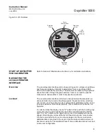
When a calibration has been initiated, the value at TP5 and TP6 is the
% O
2
seen by the cell.
Oxygen levels, as seen on the multimeter, are:
8.0% O
2
= 8.0 VDC
0.4% O
2
= 0.4 VDC
NOTE
The maximum reading available at TP5 and TP6 is 30 VDC. While the
Oxymitter will measure concentrations up to 40% the test point output will
reach a maximum of 30 VDC at a 30% oxygen concentration.
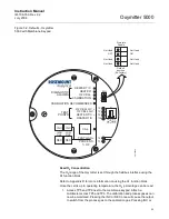
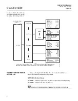
2. FOUNDATION fieldbus.
LOGIC I/O
This two-terminal logic contact can be configured either as a solid-state
relay-activated alarm or as a bi-directional calibration handshake signal to an
IMPS 4000 or SPS 4001B. The configuration of this signal depends on the
setting of the LOGIC I/O PIN MODE via FOUNDATION fieldbus or LOI. The
ten different modes available are explained in Table 4-1.
Table 4-1. Logic I/O
Configuration
*The default condition for an Oxymitter 5000 without an IMPS 4000 or SPS 4001B.
**The default condition for an Oxymitter 5000 with an IMPS 4000 or SPS 4001B.
Alarm
When configured as an alarm, this signal alerts you to an out-of-spec
condition. The output is +5 Vdc in series with a 340 ohm resistor.
For optimum performance, Emerson Process Management recommends
connecting the output to a Potter & Brumfield 3.2 mA DC relay (P/N
R10S-E1Y1-J1.0K).
Of the ten modes in Table 4-1, mode 1 through mode 7 are the alarm modes.
The factory default is mode 5 for Oxymitter 5000 units without an IMPS 4000
or SPS 4001B. In this mode, the output will signal when a unit alarm or a
CALIBRATION RECOMMENDED indication occurs.
Mode
Configuration
0
The unit is not configured for any alarm condition.
1
The unit is configured for a Unit Alarm.
2
The unit is configured for Low O
2
.
3
The unit is configured for both a Unit Alarm and Low O
2
.
4
The unit is configured for a High AC Impedance/CALIBRATION
RECOMMENDED.
5*
The unit is configured for both a Unit Alarm and a High AC
Impedance/CALIBRATION RECOMMENDED.
6
The unit is configured for both a Low O
2
and High AC Impedance/CALIBRATION
RECOMMENDED.
7
The unit is configured for a Unit Alarm, a Low O
2
, and a High AC
Impedance/CALIBRATION RECOMMENDED.
8**
The unit is configured for a calibration handshake with IMPS 4000 or SPS 4001B.
CALIBRATION RECOMMENDED will initiate the calibration cycle.
9
The unit is configured for a calibration handshake. CALIBRATION
RECOMMENDED will not initiate the calibration cycle with the IMPS 4000 or SPS
4001B.
Summary of Contents for Oxymitter 5000
Page 2: ......
Page 6: ......
Page 12: ......
Page 22: ...Oxymitter 5000 xii Instruction Manual IM 106 350 Rev 2 2 July 2008 ...
Page 42: ...Oxymitter 5000 1 20 Instruction Manual IM 106 350 Rev 2 2 July 2008 ...
Page 62: ...Oxymitter 5000 2 20 Instruction Manual IM 106 350 Rev 2 2 July 2008 ...
Page 74: ...Oxymitter 5000 4 6 Instruction Manual IM 106 350 Rev 2 2 July 2008 ...
Page 78: ...Oxymitter 5000 5 4 Instruction Manual IM 106 350 Rev 2 2 July 2008 ...
Page 94: ...Oxymitter 5000 7 6 Instruction Manual IM 106 350 Rev 2 2 July 2008 ...
Page 140: ...Oxymitter 5000 9 22 Instruction Manual IM 106 350 Rev 2 2 July 2008 ...
Page 184: ...Oxymitter 5000 B 2 Instruction Manual IM 106 350 Rev 2 2 July 2008 ...
Page 204: ...Oxymitter 5000 D 14 Instruction Manual IM 106 350 Rev 2 2 July 2008 ...
Page 222: ...Oxymitter 5000 E 18 Instruction Manual IM 106 350 Rev 2 2 July 2008 ...
Page 224: ...Instruction Manual IM 106 350 Rev 2 2 July 2008 Index 2 Oxymitter 5000 ...


