background image

Operations Manual 


FGD-MAN-0047 

January 2017 


21 


7.4.2


Calibration failure 

If the calibration procedure fails, the display shows Fail Cal, the Status 
LED alternates red/green flashes and the analog output changes back 
and forth from 3.0–3.3 mA. 

The unit remains in a failed state until 

Manual reset

. After the manual 

reset, the unit will return to normal operation based on previous 
calibration values.  


Summary of Contents for Net Safety MLP-A-SC1100

Page 1: ...Number MAN 0047 Rev 16 January 2017 Net Safety Millennium Combustible Gas Detector User Manual Models MLP A AR AD SC1100 MLP LP A AR ARS SC1100 ...

Page 2: ......

Page 3: ...e responsibility for the selection use or maintenance of any product Responsibility for proper selection use and maintenance of any Net Safety products remains solely with the purchaser and end user To the best of Net Safety s knowledge the information herein is complete and accurate Net Safety makes no warranties expressed or implied including implied warranties of merchantability and fitness for...

Page 4: ... s sole expense and Seller shall not be obligated to pay any costs or charges incurred by Buyer or any other party except as may be agreed upon in writing in advance by Seller All costs of dismantling reinstallation freight and the time and expenses of Seller s personnel and representatives for site travel and diagnosis under this limited warranty clause shall be borne by Buyer unless accepted in ...

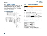
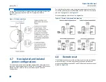
Page 5: ...ternal equipment 6 3 3 Mount 6 Section 4 Wire 7 4 1 Field installation 7 4 2 Seal 7 4 3 Connecting wires 7 4 4 Board assembly 8 4 5 Sensor and controller 8 4 5 1 Relay board 9 4 5 2 RS 485 communication 9 4 6 Sensor separation 9 4 7 Current output 9 4 8 Non isolated and isolated power configurations 10 4 9 Remote reset 10 4 10 Modbus termination 11 Section 5 Operate 13 5 1 Calibration button 15 5 ...

Page 6: ...23 8 1 Review relay settings 23 8 2 Set relay option 23 8 2 1 Steps in setting relay options 23 8 3 Enter Restricted menu 24 8 3 1 Extend sensor separation 24 8 3 2 Set low power options optional 24 8 3 3 Select display language 25 8 3 4 Modbus options 25 8 3 5 Node Address 25 8 3 6 Baud Rate 25 8 4 Alarms 25 8 4 1 Sensor fault 25 8 4 2 Sensor drift 26 8 5 Gas present 26 8 6 Cross sensitivity 26 8...

Page 7: ...29 9 2 Troubleshoot 29 9 3 Troubleshooting guide 30 Section 10 How to return equipment 32 10 1 Spare parts accessories 32 10 2 Face rotation option 33 10 2 1 Rotate PCB assembly 33 Appendix A Electrostatic sensitive device ESD 36 Appendix B Resistance table 38 Appendix C Sensor specifications 40 Appendix D Controller specifications 42 ...

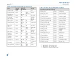
Page 8: ...minal connection 9 Table 5 1 Status LEDs Display messages and current loop 14 Table 5 2 RTU Status register 40002 Read only binary 14 Table 8 1 Default relay settings 23 Table 9 1 Troubleshooting guide 30 Table 10 1 Part numbering 32 Table B 1 Resistance table 38 Table C 1 Millennium sensor specifications 40 Table D 1 Millennium Controller specifications 42 ...

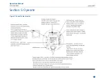
Page 9: ...igure 4 1 Securing wires 7 Figure 4 2 Millennium module boards 8 Figure 4 3 Wiring controller and sensor 9 Figure 4 4 Jumper position 10 Figure 4 5 Current source and sink drawing 10 Figure 4 6 Remote reset 11 Figure 4 7 Modbus termination jumpers 11 Figure 5 1 Controller functionality 13 Figure 7 1 Calibration Procedure 19 Figure 10 1 Non standard orientation 33 Figure 10 2 PCB assembly rotated 3...

Page 10: ......

Page 11: ...ures accurate and repeatable response in the most severe environments 1 2 The controller transmitter The Millennium Controller has an Explosion Proof Housing rated Class 1 Division 1 Groups B C and D for hazardous applications It was designed for either a 1 man intrusive calibration or 2 man non intrusive calibration The controller has convenient user interface functionality to make installation o...

Page 12: ...Operations Manual January 2017 FGD MAN 0047 2 ...

Page 13: ...ted Use common sense and refer to the regulatory publications that discuss guidelines for your industry The two most common installations options are as follows 2 2 Option 1 Locate the sensor separate from the controller using a Certified Junction Box If the Net Safety Multi Purpose Junction Box is being used refer to MAN 0081 for terminal designations The controller is located near eye level The ...

Page 14: ...y 2017 FGD MAN 0047 4 Figure 2 2 below shows the controller with sensor and the multi purpose junction box with sensor attached CCS 1 Multi purpose junction box with sensor Controller with sensor Figure 2 2 Dimensional drawing ...

Page 15: ...ainst the enclosed packing list and inspect all components for obvious damage such as broken or loose parts If you find any components missing or damaged notify the representative or Emerson immediately Millennium faceplate SC1100 sensor Ribbon connecting faceplate controller Controller housing cover Controller base housing Figure 3 1 Components ...

Page 16: ...r 3 3 Mount The controller should be mounted near eye level and be easily accessible for calibration and maintenance purposes The sensor should be placed where gas is likely to accumulate and mounted pointing downwards as shown in Figure 3 1 Ensure all devices are securely mounted taking into consideration all requirements If necessary use the face rotation option to mount the Millennium Controlle...

Page 17: ... codes and per the seal manufacturers recommended guidelines Seals are especially recommended for installations that use high pressure or steam cleaning devices in proximity to the transmitter and or sensor Water proof and explosion proof conduit seals are recommended to prevent water accumulation within the enclosure Seals should be located as close to the device as possible and not more than 18 ...

Page 18: ...ontroller If so you need only connect the power terminals Remove the controller s housing cover Connect the sensor to the sensor terminals if necessary and the power terminals to power and output signal wires Turn controller on put On Off Switch in On position Replace controller s housing cover Apply power to unit Ensure display reads Start Delay status LED is red slow flash and current output dis...

Page 19: ...is done with the aid of the sensor separation kit The sensor separation kit is composed of a Net Safety Multi Purpose Junction Box and terminal strip For terminal definitions refer to the Multi Purpose Junction Box manual MAN 0081 Shielded copper instrument wire minimum 18 AWG should be used for separations up to 75 feet Shielded copper instrument wire minimum 16 AWG should be used for separations...

Page 20: ... Pin 2 for current sink using non isolated configuration For Isolated configuration using a separate power supply to isolate the current loop the jumper must be placed over Pin 1 and Pin 2 for source and sink See Figure 4 4 and Figure 4 5 Note the jumper position for each configuration Figure 4 5 Current source and sink drawing 4 8 Remote reset If the Millennium relays are set for latching a remot...

Page 21: ...set 4 9 Modbus termination Devices can be networked in a daisy chain The device located at the end of the chain requires end of line termination Place both jumpers over the pins as shown in the Figure 4 7 below Modbus Board JP1 JP2 Figure 4 7 Modbus termination jumpers ...

Page 22: ...Operations Manual January 2017 FGD MAN 0047 12 ...

Page 23: ...Operations Manual FGD MAN 0047 January 2017 13 Section 5 Operate Figure 5 1 Controller functionality ...

Page 24: ...00 LEL Gas present 4 20 mA Red blip blink N A 1 100 full scale Failed calibration 3 0 3 3 mA Red flash Green flash Fail cal Table 5 2 RTU Status register 40002 Read only binary RTU Status registers and meaning RTUstat_fault 0x0001 Fault sensor RTUstat_low_alarm 0X0002 Low alarm tripped RTUstat_high_alarm 0X0004 High alarm tripped RTUstat_low_alarm_latched 0X0008 Low alarm latched RTUstat_high_alar...

Page 25: ...net Place and hold the magnet to the controller s housing 10 o clock position to calibrate and access the main menu Briefly place the magnet to the Controller s Housing 10 o clock position to make a selection select YES 5 3 Current loop measurement test jacks Use a standard meter to measure current loop during various states The controller s housing cover must be removed to access the test jacks R...

Page 26: ...Operations Manual January 2017 FGD MAN 0047 16 ...

Page 27: ...g the main menu There are two ways to access the main menu Calibration button found on the faceplate the housing cover must be removed to access Magnetic reed switch a magnet must be used to activate 6 2 Main menu functionality Ensure that the controller has been turned on and no fault is present Hold the magnet against the reed switch or press and hold the Calibration button until the message Swi...

Page 28: ...Operations Manual January 2017 FGD MAN 0047 18 ...

Page 29: ...ing to 100 of full scale is converted to a linear 4 20 mA output signal which can be powered from the primary dc supply of the instrument Power up the unit for at least 4 hours BEFORE the first calibration The following calibration procedure should be followed to ensure an accurate correlation between the 4 20 mA output signal and the gas concentration To compensate for distance when remotely cali...

Page 30: ...l Complete will display when calibration is completed 11 Apply clean air again to purge system Always apply test gas after calibration to verify operation 7 3 Remote calibration The preferred tubing has an inside diameter of 3 16 inches stainless steel tubing is excellent plastic tubing is good Within 10 ft 35 m a flow rate of 0 5 liters per minute can be used but 1 0 litre per minute is recommend...

Page 31: ...dure fails the display shows Fail Cal the Status LED alternates red green flashes and the analog output changes back and forth from 3 0 3 3 mA The unit remains in a failed state until a Manual reset After the manual reset the unit will return to normal operation based on previous calibration values ...

Page 32: ...Operations Manual January 2017 FGD MAN 0047 22 ...

Page 33: ...s The high and low relay configurations are set up independently of each other Table 8 1 Default relay settings 8 2 1 Steps in setting relay options There are two settings for Relay Options Low and High The fault relay is fixed as energized non latching and cannot be changed The low alarm level coil energization and latch status are set first high alarm level coil energization and latch status are...

Page 34: ...selection 3 When Are you sure YES displays press the Calibration button or use the reed switch to select The flashing YES confirms the selection 8 3 1 Extend sensor separation 1 Enter the Restricted menu Refer to Enter Restricted menu 2 When Extend Sensor Separation YES displays press the Calibration button or use the reed switch to select The flashing YES confirms the selection 3 Sensor Separatio...

Page 35: ...New Address YES and press the Calibration button or use the Reed Switch to select 4 Use the Calibration button or use the reed switch to select each of three numbers in the new address select the last number in the address first 0 thru 9 select the next number in the address 0 thru 9 select the first number in the address last e g 0 1 2 8 3 6 Baud Rate The transmission speed must be defined 1 When...

Page 36: ...y recommends that a bump test of the sensor is completed every three 3 months or immediately after a known exposure to the listed contaminants in cross sensitivity Bump testing consists of a visual inspection of the sensor applying a known gas concentration to the sensor verifying the accuracy of the response to the specifications of the sensor and alarm system simulation If the response is outsid...

Page 37: ...es a potential problem with the controller Standard electro mechanical relay outputs have Form C SPDT contacts rated five Amps at 30 Vdc 250 Vac Three relay outputs are available one for Fault one for Low alarm and one for High alarm All relays have normally open and normally closed contacts available at the output terminals The Fault relay is set for normally energized operation and is non latchi...

Page 38: ...Operations Manual January 2017 FGD MAN 0047 28 ...

Page 39: ...l scale An additional consideration is the accuracy and tolerance of the calibration gas which may be or a few percent If the calibration gas is or 10 of full scale then the reading may be from 10 7 mA 42 of full scale to 13 3 mA 58 of full scale 9 2 Troubleshoot Response to the input should be checked and if necessary calibration should be performed whenever any of the following occur Refer to Ca...

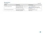
Page 40: ... s Tightly fit electronic boards Contact factory Contact factory Sensor fault displays Faulty power supply Faulty sensor Faulty sensor wiring Faulty junction box wiring Water invasion of electronics junction box Failed electronic component s Replace or correct power supply Replace sensor Correct sensor wiring at controller Correct junction box wiring Contact factory Contact factory Unstable 4 20 m...

Page 41: ...Failed electronic component s Correct relay settings in menu Correct voltage applied to relay dry contacts See Appendix C Sensor specifications for specifications Contact factory Chattering relays Mechanical relay units Voltage is below operational voltage Loose electronic boards or loose wiring Failed electronic component s Correct input voltage to unit Tightly fit electronic boards or fit wires ...

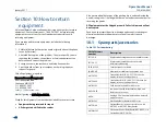
Page 42: ...e sender Also ensure a duplicate copy of the packing slip is enclosed inside the box indicating item 1 4 along with the courier and account number for returning the goods All Equipment must be Shipped prepaid Collect shipments will not be accepted Pack items to protect them from damage and use anti static bags or aluminium backed cardboard as protection from electrostatic discharge 10 1 Spare part...

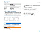
Page 43: ... Rotate PCB assembly Ensure area is declassified 1 Remove the controller s housing cover 2 Turn the power to the detector off 3 Unscrew both the knobs marked Pull Here 4 Lift controller faceplate from housing and allow to hang from ribbon cable 5 Unscrew the two metal standoffs 6 Carefully remove the PCB assembly from the housing 7 The rotator plate is secured to the bottom of the housing and is a...

Page 44: ...Operations Manual January 2017 FGD MAN 0047 34 Figure 10 2 PCB assembly rotated See Appendix A Electrostatic sensitive device ESD for handling electronic components ...

Page 45: ...Operations Manual FGD MAN 0047 January 2017 35 ...

Page 46: ... indefinite period of time followed by a sudden failure To eliminate potential ESD damage review the following guidelines Handle boards by metal shields taking care not to touch electronic components Wear grounded wrist or foot straps or ESD shoes or heel grounders to dissipate unwanted static energy Prior to handling boards dispel any charge in your body or equipment Ensure components are transpo...

Page 47: ...Operations Manual FGD MAN 0047 January 2017 37 ...

Page 48: ... 2 02 1 27 0 80 0 50 900 9 14 5 75 3 61 2 27 1 43 0 90 0 57 1000 10 20 6 39 4 02 2 53 1 59 1 09 0 63 1250 12 70 7 99 5 03 3 16 1 99 1 25 0 79 1500 15 20 9 58 6 02 3 79 2 38 1 50 0 94 1750 17 80 11 20 7 03 4 42 2 78 1 75 1 10 2000 20 30 12 80 8 03 5 05 3 18 2 00 1 26 2250 22 80 14 40 9 03 5 68 3 57 2 25 1 41 2500 25 40 16 00 10 00 6 31 3 97 2 50 1 57 3000 30 50 19 20 12 00 7 58 4 76 3 00 1 88 3500 ...

Page 49: ...10 30 6 50 4 08 7000 71 10 44 70 28 10 17 70 11 10 7 00 4 40 7500 76 10 47 90 30 10 19 00 12 00 7 49 4 71 8000 81 20 51 10 23 10 20 20 12 70 7 99 5 03 9000 91 40 57 50 36 10 22 70 14 30 8 99 5 65 10000 102 00 63 90 40 20 25 30 15 90 9 99 6 28 Resistance shown is one way This figure should be doubled when determining closed loop resistance ...

Page 50: ...0 C to 85 C Weight 0 2 lb 0 1 kg Enclosure material Powder coated or anodized aluminum optional stainless steel Range of detection 0 to 100 LEL of most hydrocarbons and hydrogen Accuracy 3 LEL up to 50 LEL 5 LEL above 50 LEL Response time 10 seconds to T50 30 seconds to T90 Linearity repeatability 3 LEL 2 LEL Certification Class 1 Division 1 Groups B C and D T5 Type 3R Ex d IIB H2 T5 Gb Performanc...

Page 51: ...Operations Manual FGD MAN 0047 January 2017 41 ...

Page 52: ...0 120A after 2ms 4 6A 10µs 40µs 0 32A after 2ms 4 8A 10µs 40µs 0 112A after 2ms Operating voltage 10 5 to 32 VDC Operating temp range Operational 67 F to 185 F 55 C to 85 C Certified 40 F to 185 F 40 C to 85 C Humidity range 0 to 100 relative humidity non condensing Enclosure material Powder coated copper free cast aluminum or stainless steel Weight without sensor Aluminum enclosure 5 3 lb 2 4 kg ...

Page 53: ...Notes ...

Page 54: ...Notes ...

Page 55: ......

Page 56: ...The Emerson logo is a trademark and service mark of Emerson Electric Co Net Safety is a trademark of one of the Emerson Process Management family of companies All other marks are the property of their respective owners The contents of this publication are presented for information purposes only and while effort has been made to ensure their accuracy they are not to be construed as warranties or gu...

Reviews: