


34
User Manual 10H52188UM60 - Rev. 2 - 09/2012
Parallel UPS Installation And Commissioning
Liebert NXC
Chapter 4
Parallel UPS Installation And Commissioning
This chapter describes the features, requirements, installation and commissioning of the parallel system.
The UPS parallel system provides the user with N + X (2
≤
N + X
≤
4) parallel configuration, N stands for the basic parallel sets, X
stands for the redundant sets.
4.1
Features
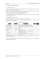
1. The software and the hardware of each UPS in parallel system are the same as those of the single UPS. The basic parameters
of the parallel system (refer to 4.4.2) and the detailed parameters can be set through the Service Software (for service
engineers only). For all UPS of the parallel system, the requirements of the parameter settings are same.
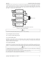
2. The parallel cables form a ring connection (Refer to 4.3.2
for details) to provide reliability and redundancy for system. The
intelligent parallel logic provides the user with maximum flexibility. For example, each UPS in the parallel system can be
switched off or on in random order; seamless transfer can be achieved between Normal mode and Bypass mode, and the
transfer is automatically recoverable: that is, after the overload condition is removed, the system will return to the original
operation mode automatically.
3. The total load of the parallel system can be queried through the LCD of each UPS.
4.2
Requirements
A UPS system composed of multiple parallel-connected UPS units is equivalent to a large UPS system. Nevertheless, it provides
increased system reliability. To ensure equal utilization of all UPS units and compliance with relevant wiring regulations, the
following requirements must be met:
1. All single UPS must have the same capacity and must be connected to the same bypass source.
2. The bypass input power and rectifier input power must be connected to the same neutral line input terminal.
3. If a residual current detector (RCD) is required, it must be set correctly and installed before the same neutral line input
terminal, or it must monitor the protective earth current of the system. Refer to
Safety Manual
.
4. The outputs of all single UPS must be connected to the same output bus.
5. As the UPS parallel system is not fitted with any auxiliary contact detection devices for the UPS unit output MCB or
maintenance bypass MCB. Removing the single UPS from the parallel system before maintenance and adding the single UPS
into the parallel system after maintenance must be conducted strictly following the procedures provided in 6.2. Failure to
observe this may affect the load power supply reliability.
4.3
Connecting Power Cables
For each single UPS of the parallel system you need to configure the MCB and cable respectively, refer to 3.4 for the
specification.
4.3.1
Connecting I/O Cables
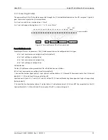
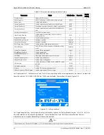
The UPS power cables are connected to the I/O terminal block of the UPS rear panel, the layout of the I/O terminal block is
shown in Figure 3-4.
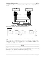
Power distribution mode
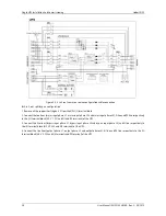
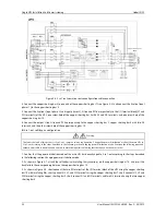
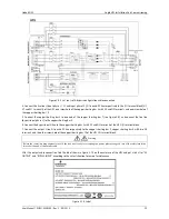
The I/O cable connections are divided into four types: 3-in 3-out, common source configuration (factory default), 3-in 3-out,
split-bypass configuration, 3-in 1-out, common source configuration, 3-in 1-out, split-bypass configuration. The input and
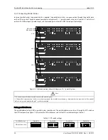
output cable connection procedures of the four power distribution modes are as follows.
Distribution for the parallel system


