


Type 2500
Instruction Manual
Form 1013
December 2005
18
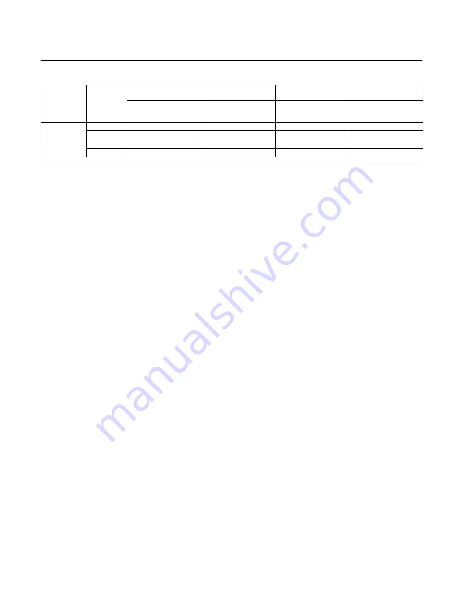
Table 6. Recommended Settings For Pre-Startup Checks
MOUNTING
ACTION
RECOMMENDED RAISE LEVEL SETTING
FOR TYPE 2500 CONTROLLER
RECOMMENDED ZERO ADJUSTMENT SETTING FOR
TYPE 2500T TRANSMITTER
For Predetermined
PROPORTIONAL BAND
Dial Setting of 10
(1)
For Predetermined
PROPORTIONAL BAND
Dial Setting of 0
(1)
For Predetermined
SPECIFIC GRAVITY Dial
Setting of 1.0
(1)
For Predetermined
SPECIFIC GRAVITY Dial
Setting of 0
(1)
Right-hand
Direct
3.0 to 3.5
4.0 to 4.5
1.5 to 2.0 to right
0.5 to 1.0 to right
Reverse
6.5 to 7.0
0.5 to 1.0
1.5 to 2.0 to left
4.0 to 4.5 to right
Left-hand
Direct
3.0 to 3.5
4.0 to 4.5
1.5 to 2.0 to left
0.5 to 1.0 to left
Reverse
6.5 to 7.0
0.5 to 1.0
1.5 to 2.0 to right
4.0 to 4.5 to left
1. For proportional band dial settings between 10 and 0 or for specific gravity dial settings between 1.0 and 0, interpolate the value.
Several steps in these calibrating procedures require
setting the process variable at its minimum and
maximum limits, according to table 5.
Note
If the process cannot be varied readily
or the Wet Calibration method cannot
be used in the following steps, be sure
to use the proper sequence of correct
weights as found in the Determining
Amount of Suspended Weight
procedure. Whenever the following
steps require particular prestartup
checks, refer to the appropriate
procedures for: Type 2500 Controller
or 2500T Transmitter, Type 2500S
Controller, or Type 2503 Controller.
Type 2500 Controller and 2500T
Transmitter
1. Turn on the supply pressure and check that it is
set according to the appropriate prestartup checks
procedure.
2. Make sure that the PROPORTIONAL BAND or
SPECIFIC GRAVITY adjustment is at the setting
determined according to the appropriate prestartup
check procedure.
3. Adjust the RAISE LEVEL (Type 2500) or ZERO
ADJUSTMENT (Type 2500T) to the appropriate
value per table 6. This table gives recommended
settings based on maximum and minimum possible
PROPORTIONAL BAND (Type 2500) or SPECIFIC
GRAVITY (Type 2500T) settings. If an intermediate
PROPORTIONAL BAND or SPECIFIC GRAVITY
setting is necessary, extrapolation may be used to
determine a new RAISE LEVEL or SPECIFIC
GRAVITY setting.
4. Set the process variable to the minimum value of
the input range as shown in table 5. For
constructions with an indicator assembly, make sure
that the pointer is over the LOW mark.
Note
In the following step, the alignment
screw (key 33, figure 16) must always
remain screwed in far enough to
provide spring tension on the
underside of the alignment screw
head.
5. Adjust the flapper (key 32, figure 16) to obtain the
appropriate pressure listed below. For coarse flapper
adjustment, loosen the hex nut (key 40, figure 16)
and rotate the flapper assembly about the torque
tube shaft. For fine flapper adjustment, turn the
flapper alignment screw (key 33, figure 16).
D
For Direct Acting Type 2500, 2500T,
0.2 bar
(3 psig) for a 0.2 to 1.0 bar (3 to 15 psig) output or
0.4 bar (6 psig) for a 0.4 to 2.0 bar (6 to 30 psig)
output.
D
For Reverse Acting Type 2500, 2500T
, 1.0
bar (15 psig) for a 0.2 to 1.0 bar (3 to 15 psig) output
or 2.0 bar (30 psig) for a 0.4 to 2.0 bar (6 to 30 psig)
output.
6. Visually examine the nozzle and flapper to
ensure the nozzle is as square as possible with the
flapper. The nozzle can be realigned by loosening
the Bourdon tube mounting screws (key 45,
figure 16) and rotating the Bourdon tube slightly. If
the nozzle is realigned, tighten the mounting screws
and repeat step 5.
7. Set the process variable to the maximum value of
the input range as shown in table 5.
8. The output pressure should be:
D
For Direct Acting Type 2500, 2500T
, 1.0 bar
(15 psig) for a 0.2 to 1.0 bar (3 to 15 psig) output or
2.0 bar (30 psig) for a 0.4 to 2.0 bar (6 to 30 psig)
output.


