Emerson KHZ506 User Manual Download Page 14


Tube Size


Max distance between 

2 clamp support


12.7mm (1/2 inch)


1.20 m


16.0mm (5/8 inch)


1.50 m


22.0mm (7/8 inch)


1.85 m


28.5mm (1 1/8 inch)


2.20 m


OUTSIDE


INSIDE UNIT


End of Tube


During brazing 
protecthousing 
withdampcloth

During brazing 
pull back fire 
insulation


All interconnecting pipes should be of refrigeration grade, clean, dehydrated and must remain capped at 
both ends until installation. Even during installation, if the system is left for any reasonable period (say 
two hours), pipes should be re- capped to prevent moisture and contaminants from entering the system. 

Do not assume that the service connection sizes on the unit (at the service valves) are the correct size to 
run your interconnecting refrigeration pipes. The service valve sizes have been selected for convenience 
of installation and in some cases (larger units) these may be considered too small. However, for the very 
short pipe run within our units, these service connection sizes are adequate. 

The pipe should be sized to ensure optimum performance and good oil return. The sizing must also take 
into account the full capacity range through which this particular unit will need to operate. 

Pipe runs should be kept as short as possible, using the minimum number of directional changes. Use 
large radius bends and avoid trapping of oil and refrigerant. This is particularly important for the suction 
line. The suction line should ideally slope gently towards the unit. Recommendation slope is 
1/200~1/250. P traps, double risers and reduced pipe diameters may be required for suction lines where 
long vertical risers cannot be avoided. All pipes should be adequately supported to prevent sagging 
which can create oil traps. 
The recommended pipe clamp support distance is shown in the table. 

Refrigeration Piping Installation 

Brazing Recommendations 

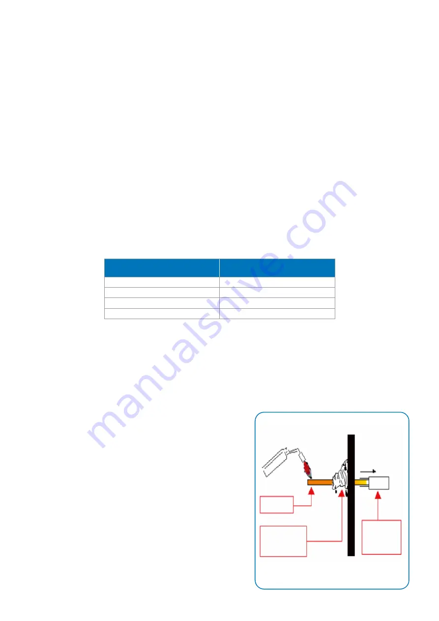
Maintain a flow of oxygen-free nitrogen through the system at a very low-pressure during brazing. 
Nitrogen displaces the air and prevents the formation of copper oxides in the system. If copper 
oxidization is allowed to form, the copper oxide material can later be swept through the system and 
block screens such as those protecting capillary tubes, thermal expansion valves, and accumulator oil 
return holes. This minimizes any entry of contaminants and moisture. 

•  Remove the liquid line connection cap. 
•  Then remove the suction connection cap. 
•  Open both valves midway. Care should be taken to 

avoid the holding charge from releasing too quickly. 

•  Be sure tube fitting inner diameter and tube outer 

diameter are clean prior to assembly. 

•  Since both tubes are extended from the condensing 

unit housing, we recommend insulating the housing by 
using a wet cloth on the copper tubing. 

•  Recommended brazing materials: a copper / 

phosphorous or copper/ phosphorous / silver alloy rod 
should be used for joining copper to copper whereas to 
join dissimilar or ferric metals, use a silver alloy rod, 
either flux coated or with a separate. 

•  Use a double tip torch. 

12

Summary of Contents for KHZ506

Page 1: ...ZSI Scroll Condensing Units User Manual ...

Page 2: ...on 10 Qualified Oils Refrigerant 10 Location and fixing 11 Installation Clearance 11 Refrigeration Piping Installation 12 Brazing Guideline Wiring Diagram Start Up and Operation Leak Test 15 System Evacuation Refrigerant charging Charge limit 16 Maintenance Application Tips 18 System Troubleshooting 21 System Start Up and Operation Check Sheet 23 Contact Lists 24 Table of Content 12 13 15 ...

Page 3: ...r use only by qualified and or experienced personnel or technicians certified by us These instructions are general in nature for this family of products and due to our policy of continuous improvement some of the details may not apply to the unit that you are installing If in doubt please consult your local sales office quoting unit model and serial number as shown on the name plate In case of amb...

Page 4: ...contact During maintenance if Brazing or De brazing process is required Kindly ensure that there should not be any refrigerant oil inside the system pipe or the brazing area Company shall not be responsible for any kind of accidents occur at sites due lack of sense of responsibility Mis handling Wrong practice of installation and not following the instructions as mentioned above Do not pressurize ...

Page 5: ...apacity at 60Hz Btu hr Scope of Supply KH Motor Circuit Code Description 5 3 Phase Application Code Description L Low Temperature Voltage Range Code Description E 400V 380 420 50Hz 3Ph Compressor Family Code Description Z Scroll Compressor Refrigerant Code Description L R404a Code Description R CDU with Serviceable Chassis 3 ...

Page 6: ...eliable operation On board CoreSense electronics unit for diagnostics and protection to assist contractors troubleshoot in the field Uses Liquid Injection technology controlled by CoreSense to protect the compressor from high discharge temperature LED display alerts user of DLT sensor status and EXV operation enabling easier troubleshooting Tropicalized for Indian climate to operate at higher ambi...

Page 7: ...platform the CoreSense Control Board CoreSense regulates liquid injection by sensing the Discharge Line Temperature DLT to widen the operating envelope and enhance the product reliability It also features LED display that alerts the user of sensor status and Electronic Expansion Valve EEV operation The board will be used to turn the compressor on off based on the demand signal from low pressure sw...

Page 8: ...Operate EXV Manually Short Push 2s Up or Down to open or close EXV by one step Long Push Up and Down to open and close EXV rapidly LED2 will flash when EXV is opening and will remain on when EXV is fully open LED3 will flash when EXV is closing and will remain on when EXV reaches minimum opening Push Up and Down together for 5 seconds to revert to Auto Mode Board will automatically revert to Auto ...

Page 9: ...Sight glass CoreSense along with EXV Fan motor Serviceable chassis Blue fin coated condenser Receiver with valve Accumulator Oil separator Adjustable LP HP switch Liquid Line filter drier Moisture Indicator CDU service valves Electrical Terminals Crank Case Heater Important Note Above given Scope of supply comes with our Standard designed Models For any customized requirement of additional accesso...

Page 10: ...ion Connection Kg dBA KHZ506LRL 1 160 Watts 230V 1Ph 50Hz 4 6 1043 x 440 x 805 656 402 5 8 3 8 96 5 60 KHZ508LRL 656 402 5 8 3 8 96 5 62 KHZ509LRL 656 402 5 8 3 8 96 5 63 KHZ511LRL 656 402 7 8 1 2 111 68 KHZ514LRL 656 402 7 8 1 2 140 71 KHZ515LRL 656 402 7 8 1 2 140 71 KHZ518LRL 2 5 7 1043 x 440 x 1140 656 402 7 8 1 2 169 73 KHZ521LRL 656 402 7 8 1 2 190 74 Power Input is 400V 3Ph 50Hz Figure 3 KH...

Page 11: ... 2 5 Sq mm ZSI14KQE TFM 380 420V 50 Hz 3Ph 12 1 12A 2 5 Sq mm ZSI15KQE TFM 380 420V 50 Hz 3Ph 12 7 18A 2 5 Sq mm ZSI18KQE TFM 380 420V 50 Hz 3Ph 15 22A 4 0 Sq mm ZSI21KQE TFM 380 420V 50 Hz 3Ph 19 3 22A 4 0 Sq mm Always use AC 3 Category Contactor with above mentioned rating in table Refer below the operating envelope of the KHZXXXLRL CDU models Figure 4 Operating Envelope for KHZXXXLRLModels Refr...

Page 12: ...y qualified personnel who are familiar with local codes and regulations and experienced with this type of equipment As lifting equipment is required ensure that it is suitable for purpose certified and that the operators are qualified to use it Safe working methods are identified and operator have suitable PPE s Ensure the working area has adequate ventilation during brazing procedures Disconnect ...

Page 13: ...er each individual case carefully Ideally the unit should be mounted on a solid concrete slab with anti vibration pads between unit feet and concrete Ensure that there is no obstruction to air flow into or out of the unit Remove obstacles which block air intake or discharge The location must be well ventilated so the air can pass properly through condenser by maintaining the proper condensation in...

Page 14: ... suction line should ideally slope gently towards the unit Recommendation slope is 1 200 1 250 P traps double risers and reduced pipe diameters may be required for suction lines where long vertical risers cannot be avoided All pipes should be adequately supported to prevent sagging which can create oil traps The recommended pipe clamp support distance is shown in the table Refrigeration Piping Ins...

Page 15: ...10 Wiring Diagram 2 Fans Unit 13 ...

Page 16: ...Wiring Diagram Single Fan Unit 14 ...

Page 17: ... conditioning them before charging with refrigerant and the losses associated with improper evacuation erodes system efficiency as well as costly for the installers A 2 stage vacuum pump along with a micron gauge is recommended in performing evacuation The quality of vacuum is not determined by time a micron gauge must be used since it is the only device that accurately reads the vacuum pressure d...

Page 18: ... charge 6 Now open the liquid service valve off the back seat With a good vacuum in the system system will in take 60 70 of the refrigerant required in the system without running the compressor 7 The compressor can then be started and the unit continued to be charged with liquid refrigerant through the suction service valve The quantity of charge should always be measured See note 8 The system nee...

Page 19: ...e table below for the approximate Refrigerant holding capacity of Condensing Unit Refrigerant Charge KHZ506LRL EX 4 10 KHZ508LRL EX 4 10 KHZ509LRL EX 4 10 KHZ511LRL EX 4 10 KHZ514LRL EX 4 10 KHZ515LRL EX 4 10 KHZ518LRL EX KHZ521LRL EX 4 54 4 54 17 ...

Page 20: ...ll joints should be checked for leaks during site visits All joints should be leak tested once a year Condenser Fan s and Motor s An annual inspection of these items is recommended Fastenings may loosen bearings may wear and fans may require cleaning of solid deposits which can cause imbalance WARNING TURN OFF OR DISCONNECT THE ELECTRICAL POWER SOURCE BEFORE CLEANING THE CONDENSER Application Tips...

Page 21: ...al accessories for CDU Compressor model recommended by Company Check the electrical connections if they are properly attached secured and properly tightened Make sure all panels are secure and panel screws are properly tightened Check that the ampere draw doesn t exceed the amperage specified on the nameplate Check the phase unbalance if there is a three phase connection In single phase compressor...

Page 22: ...0 22 8 9 1 38 8 6 14 4 29 1 56 4 23 7 9 7 39 8 7 13 9 30 0 57 9 24 5 10 2 40 9 8 13 3 31 0 59 3 25 4 10 2 40 9 9 12 8 31 9 60 8 26 2 11 4 43 1 10 12 2 32 8 62 3 27 1 12 0 44 3 11 11 7 33 8 63 9 28 0 12 6 45 4 12 11 1 34 8 65 4 29 0 13 2 46 6 13 10 6 35 8 67 0 29 9 13 8 47 8 14 10 0 36 8 68 6 30 9 14 4 49 0 15 9 4 37 8 70 2 31 8 15 1 50 2 16 8 9 38 8 71 9 32 8 15 7 51 5 17 8 3 39 9 73 5 33 8 16 4 5...

Page 23: ...voltage Defective overload protector Refrigerant undercharge At compressor terminals voltage must be 10 of nameplate marking when unit is operating Replace check for correct voltage Add refrigerant High head pressure Low suction pressure Restriction in liquid line expansion device or filter drier Lack of sufficient indoor airflow Remove or replace defective component Clean check filters registers ...

Page 24: ...ture in the system Liquid Flood back in the compressor Any Contamination Oil Dilute Replace Replace Check for correct voltage at compressor check and tighten all connections Recover refrigerant evacuate and recharge replace filter drier Ensure proper load Check oil quality replace with new oil do the commissioning as per procedure Compressor trip on IOLP Leakage in the System Compressor Stuck JAM ...

Page 25: ... from Evap Client Details Facility Customer Name Address Contact Details Installer Installation Date Condensing Unit Info CDU Model Serial Number CDU Location Indoor Unit Make Model System Details Room Case ID Pipe Length approx OAT Start Up Check PSI Leak Test PSIG Duration Hours System is Leak Tight Y N Triple Evacuation Y N Micron Gauge Reading microns Total Evacuation PSIG of Hrs Refrigerant T...

Page 26: ... Pune 411 057 Tel 91 20 4200 2000 Fax 91 20 4200 2099 Pvt Ahmedabad Emerson Climate Technologies India Ltd C o Agility Logistics Pvt Ltd Old Survey No 753 756 New Survey No 155 Off Cadila Estate Off Hotel Tulsi National Highway No 8 Aslali Taluk Daskroi Ahmedabad 382427 Tel 079 30924722 7600098528 Pvt ...

Reviews: