background image

3

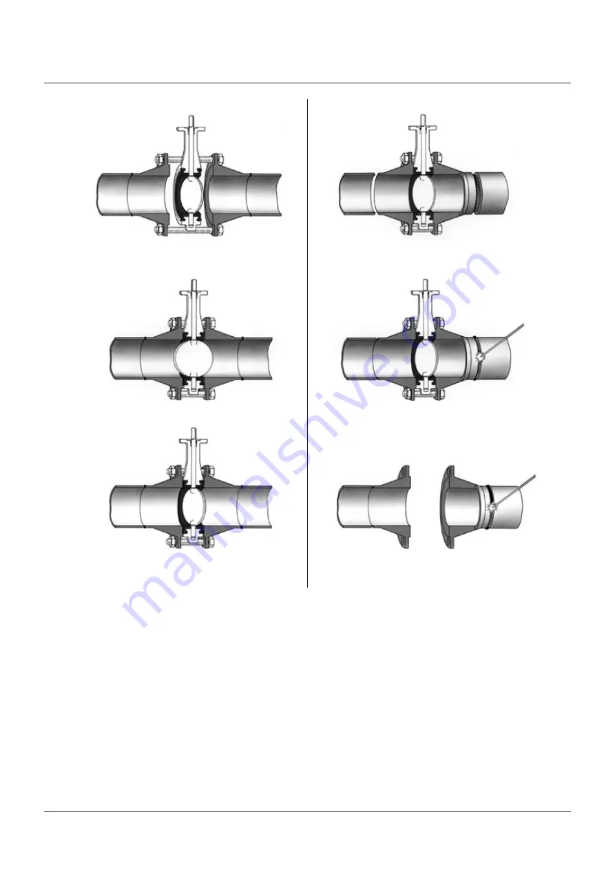
ExISTINg SYSTEm

NEW SYSTEm

1. spread the flanges with the adequate tooling. 

insert some flange bolts to bear the valve.

1. Center a flange-valve-flange assembly between 

the pipes.

2. Open the valve and remove the flange spreads.

2. tack weld the flanges to the pipes.

3. Close the valve clockwise, return to open position 

and cross-tighten all bolting.

3. remove the valve and finish weld. install the valve 

according to the procedure in the left column.

Installation in a new system (see diagrams)

it is common practice to use the valve to help in alignment of the flanges 
prior to welding the flanges into the pipeline. in such cases, the following 
instruction applies:
1.  Open the valve until the disc is free of the seat but still contained 

within the face to face of the valve.

2.  align both mating flanges with the valve center line and secure in 

position using the flange bolts.

3.  Position the flange/valve/flange assembly in the pipeline.
4.  tack weld the flanges to the pipeline.
5.  remove the flange bolts and the valve.
6.  Finish weld the flanges to the pipeline and allow to cool fully.
7.  Follow the procedure for installation in an existing system.

KEYSTONE

 Figure 990/991 ButterFly valves

InstallatIon, operatIon and maIntenance InstructIons

WarNINg

Do not finish weld the flanges to the pipeline with the valve still assembled 
to the flanges as this will result in serious damage to the valve seat.

Summary of Contents for Keystone 990

Page 1: ...rdance with the Keystone Chemical Compatibility list 2 Storage When valves are to be stored for some time 2 months or more before being fitted storage should be in the original delivery crates or cases Storage conditions The valves should be stored off the ground in a clean dry indoor area Protect the valve from temperature and humidity extremes and exposure to excessive dust moisture vibration de...

Page 2: ...on in pipeline Figure 990 991 valves are bi directional and there is no need to identify upstream and down stream orientation Figure 990 991 valves can be installed in vertical or horizontal pipelines and any intermediate orientation There is no restriction on the valve stem position vertical horizontal or oblique although for slurry service and media which have a tendency to deposit sediment the ...

Page 3: ...to the pipeline In such cases the following instruction applies 1 Open the valve until the disc is free of the seat but still contained within the face to face of the valve 2 Align both mating flanges with the valve center line and secure in position using the flange bolts 3 Position the flange valve flange assembly in the pipeline 4 Tack weld the flanges to the pipeline 5 Remove the flange bolts ...

Page 4: ... to 98 C for 30 minutes to give enough flexibility for assembly Recommended tightening torques for body screws Valve size DN Bolt size Tightening torque Nm KEYSTONE Figure 990 991 Butterfly valves Installation operation and maintenance instructions 3 Insert the long end of the stem into one of the transverse seat holes using a twisting action If possible a smear of silicone grease on the stem will...

Page 5: ...to account the following factors and any other factors which are not listed here but known to be relevant to the safe operation of the installation Parts list 1 Bushing 2 Shaft seal 3 Upper body 4 Seat 5 Disc stem 6 Lower body 7 Body screws 7 Operation 1 F990 991 valves are opened and closed by turning the top of the stem through 90 using a lever or a gearbox or a quarter turn actuator 2 Conventio...

Page 6: ...rson logo are trademarks and service marks of Emerson Electric Co All other marks are the property of their respective owners The contents of this publication are presented for informational purposes only and while every effort has been made to ensure their accuracy they are not to be construed as warranties or guarantees express or implied regarding the products or services described herein or th...

Reviews: