ADDRESSING THE WM NEXTGEN CASE CONTROLLER
1.
Press any button to wake the Visograph.
2.
Press and Hold the 4
th
button from the left for about 5 seconds
3.
Press the 2
nd
button from the left to select
System
Configuration
4.
Press the 1
st
button from the left to select
System
5.
Press
↓
until
MSTP ADDR
is highlighted.
6.
Press the
button and the
MSTP ADDR
will start
blinking.
7.
Use the ↑
↓
arrows to select the desired address.
8.
Press the
button to lock in the desired address.
9.
Right Arrow until you see
Rack ID
10. Press
when
Rack ID
is highlighted and the arrow up or
down to select the rack then press
again
11. Arrow down to
Circuit #
and press
then use
↑
↓
arrows
to select
Circuit #
then press
12. Arrow down to
CASE ID
and press set then use the
↑
↓
arrows
to select Case Identifier then press
. (Ex. a, b, c, d)
13. Press the
button until back to the home screen.
14. Do not reboot the case controller, it will reboot on its own in 7
mins. Wait for the case controller to reboot before moving
forward
SETTING UP THE E2E COMM PORTS
1. From the E2 home screen, press
Menu-7-3-1
to go to the
general controller info setup screen.
2. Press F2 twice to move to the
C3: Serial tab
.
3. Highlight the COM connection to be used for NextGen case
controller communications.
4. Press F4 then select
BacNET MSTP-1
or the next available
BacNET MSTP port to setup the port for NextGen
communications.
5. Use the down arrow key and highlight the com baud rate.
Press the F4 button and make sure it is set to
19.2 kbaud
.
6. Press the F2 button to go to the
C8: BACnet
tab
7. Verify that the Max Master is set to
40
or the highest possible
Master MSTP address.
8. APDU timeout should be set to
30
seconds
9. APDU retries should be set to
3
10. Press the
)
button to save the settings.
COMMISSIONING THE I-PRO CC WITH THE E2E
1.
Login as follows:
1.
UserName:
USER
2.
Password:
PASS
2.
From the Network Summary screen, highlight the first Case
Controller device and press F4 for commissioning.
3.
E2E will scan the comm. loop for all available case
controllers.
4.
Refer to the address sheet for the
MAC ID #
5.
Scroll down and highlight the corresponding
MAC ID #
and
press Enter.
6.
Once the device is commissioned, addressed and wired
properly, the device should come online on the E2 Network
summary screen.
XEV20D SETUP
1.
XEV20Ds should always be addressed 2 (XEV20D_1) and
3 (XEV20D_2).
2.
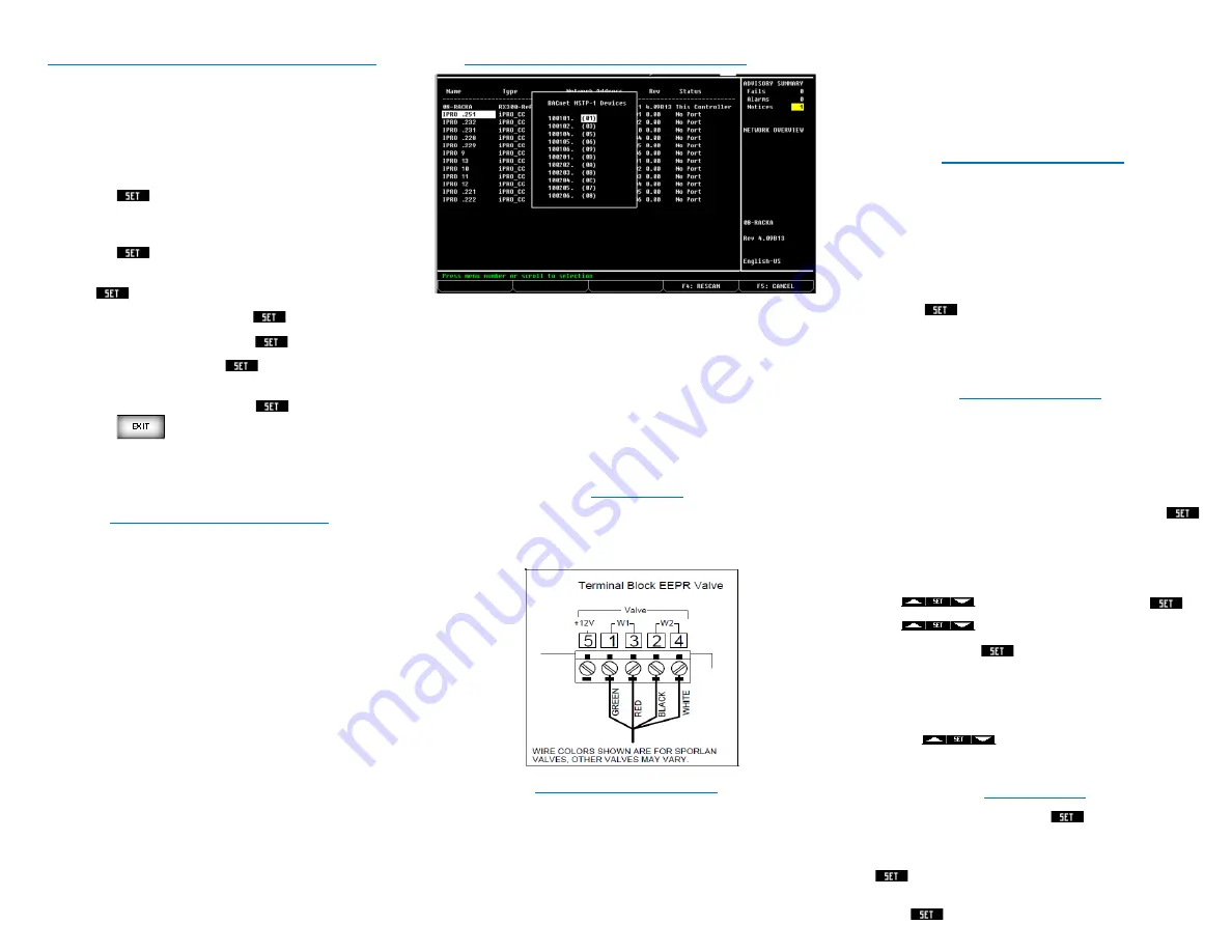
See wiring detail below for Sporlan Valve connection.
COMMON WIRING PRACTICES
1.
Shield wire should be soldered and heat shrank together
at each device.
a.
Do not terminate at the device in the middle of the
communications loop.
2.
Verify the Remote Display is wired correctly on both ends.
3.
Do not leave bare wire exposed when terminating
connectors.
4.
Shield wires should be soldered and heat shrank.
5.
22/2 wire is supplied by Emerson with part number
135-0600
6.
18/4 wire is supplied by Emerson with part number
135-2832
EEPR AND EEV CALIBRATION
1.
Once the XEV20D is online with the case controller and
the case controller is online with the E2E, the EEPR valve
needs to be Calibrated
2.
Go to the
‘Command’
selection from the
‘Main Menu’
,
use the
↓
arrow and highlight ‘
Calibrate EEPR
or
Calibrate EEV’
command
3.
Use the
↑
↓
arrows to change the value to
ON
4.
Press
again to begin calibration
5.
Use the
↑
↓
arrows to change the value back to
OFF
.
6.
Once you turn the value to
ON
and press set you can
change the value back to
OFF
OVERRIDING OUTPUTS
1.
Press any key to light up the Visograph screen
2.
Press and Hold the 4
th
button from the left for 3 seconds to
enter main menu
3.
Press the same key to select
COMMAND.
All case controller
overrides are performed from the command menu
4.
Highlight the override you wish to perform and press
a.
To override the fans, highlight
FanOver
b.
To override the lights, highlight
LightOver
c.
To override the refrigeration output, highlight
RefOver
d.
To override the defrost output, highlight
DefOver
5.
Use
to change to enable and press
6.
Use
to highlight the override status you wish to
change and press
a.
To turn on the fans, highlight
FanOn
b.
To turn on the lights, highlight
LightOn
c.
To turn on the refrigeration output, highlight
RefOn
d.
To turn on the defrost output, highlight
DefOn
7.
Use the
arrows to change to
ON
8.
Use the same steps in reverse to set back to
DISABLE
and
OFF
EEPR OVERRIDE
1.
Highlight
EEPROver
and press
2.
Use the ↑
↓
to change to desired value
3.
After testing is complete, highlight
EEPROver
and press
4.
Set value back to - 1
5.
Press


