background image

3

The family of GO USB Loggers are configurable temperature and humidity devices for your 


cold chain needs.

An accompanying configuration software allows users to customize the logger to meet specific 
customer requirements. Data gathered and stored is easily accessible via a secure PDF file and  
available to share with key stakeholders. Time stamp recordings at the end of the PDF document 

create an audit trail of logger events.

Introduction

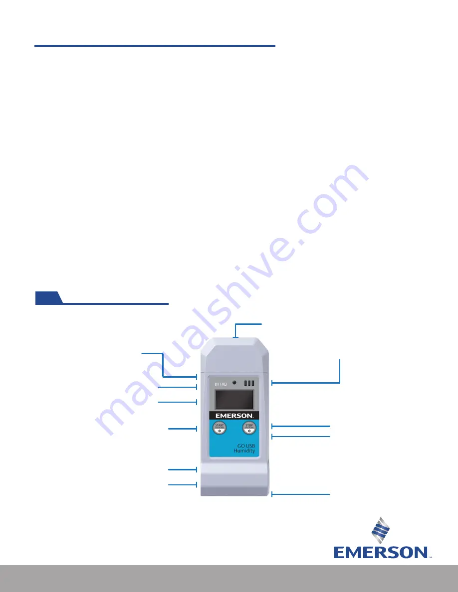
Understanding the Device

LED light

(Green = On, Red = Alert)

USB connector cover

GO USB Humidity (TH1XD)

Humidity venting hole

Start/Stop

Hang strap connector (side)

Operating Instructions (back side)

Battery compartment (back side)

Probe jack 

(only for TP1XD)

LCD Display

(Navigation buttons)

Serial number 
(bottom side)

Loggers come pre-configured from the 

factory with the following settings:

•  Alerts: None
•  Recording interval: 5-minutes
• 

Memory mode: Stop when full

What’s in the box

•  Five GO USB Loggers
•  Five ER14250 (1/2 AA) Lithium batteries
•  Five hang straps
•  Only TP1XD model: Five dry ice probes
• 

Only TP1XD model: One calibration certificate

Summary of Contents for GO USB Humidity

Page 1: ...GO USB Loggers User Manual Cargo Monitoring Solutions ...

Page 2: ...Information 5 Battery Installation 6 Operating Instructions 6 7 GO USB Probe TP1XD Model Custom Instructions 8 File Names and Extensions 9 Understanding the PDF Data File 9 12 Configuration Software 13 Using the Software 13 15 Troubleshooting and FAQ s 16 17 Technical Support 18 ...

Page 3: ...Introduction Understanding the Device LED light Green On Red Alert USB connector cover GO USB Humidity TH1XD Humidity venting hole Start Stop Hang strap connector side Operating Instructions back side Battery compartment back side Probe jack only for TP1XD LCD Display Navigation buttons Serial number bottom side Loggers come pre configured from the factory with the following settings Alerts None R...

Page 4: ...TP1XD LCD Display Navigation buttons Serial number bottom side Understanding the Device USB connector cover GO USB Probe TP1XD Start Stop Hang strap connector side Operating Instructions back side Battery compartment back side Probe jack only for TP1XD LCD Display Navigation buttons Serial number bottom side LED light Green On Red Alert LED light Green On Red Alert ...

Page 5: ...iod AVG Average ambient temperature and humidity TH1XD ambient temperature T1XD or ambient temperature and probe temperature TP1XD during the recording period MKT Mean Kinetic ambient temperature the logger and probe TP1XD has experienced during the recording period I Current interval setting P Current probe temperature value TP1XD only C If logger is configured to display Celsius F If logger is c...

Page 6: ... and a REC symbol will appear on the LCD to indicate successful activation The LED light will flash intermittently to indicate active recording In the event of an alert the LED will flash a red color The unit can be configured to alert with sound You may disable the sound by pressing and holding the STOP button for 0 5 seconds To stop recording press and hold Stop for 3 seconds and release The REC...

Page 7: ...y If an attempt to delete the PDF or CSV file is made reports will auto generate next time the logger is connected to a PC To cycle through the LCD information click short press either the Start or Stop button Navigation arrows indicates direction of information You may wish to create Marked events on your PDF and CSV report to indicate an event or occurrence To create a marked event simultaneousl...

Page 8: ... number of the logger The serial number is found on the flag sticker of the probe The serial number of the USB logger is found at the bottom of the logger Please note Failing to match the probe to the correct logger will not prevent use of probe but may have an adverse effect on calibration accuracy GO USB Probe TP1XD Model Custom Instructions ...

Page 9: ...ta File Once connected to your PC via USB a data report similar to the one below is created 1 The configuration section of the PDF report refers to the temperature and humidity limits and recording interval configured via the configuration software 2 Fixed information refers to firmware version model and serial number This information is fixed and cannot be altered via software 3 Logging summary r...

Page 10: ...sholds have been configured they are displayed and color coded A legend can be found below the graph as a reference TP1XD graph example Each consecutive page following the graph contains the time and measurement point collected TP1XD data table example Understanding the PDF Data File cont d ...

Page 11: ... time File generation times PC connect and disconnect times Marked event times TP1XD audit trail page example Marked events appear on the PDF report as red dots on the graph and in the running table Two marked events This page shows all interactions with the logger such as Understanding the PDF Data File cont d ...

Page 12: ...ed to create additional graphs or import data to a repository of choice 3 TH1XD CSV file example 3 Due to their editable nature CSV files are not recommended to be used as a primary source of information when sharing amongst organization or parties within your organization Understanding the PDF Data File cont d ...

Page 13: ...asked to select a preferred language Select the preferred language and click Enter The software will now launch Download GO USB Logger Software Configuration Software While the all the loggers come pre configured and ready to use with default settings the GO USB loggers are configurable to meet your cold chain needs If you wish to configure a logger please ensure that the product has been stopped ...

Page 14: ... Recording mode selection Stop_Recording Logger will stop when memory is full Continuous_FIFO first in first out Logger will replace first recorded data points with last recorded data points 3 LCD Time Display Current Logger LCD will display current time as configured in the software Duration Logger LCD will display total running time from activation Using the Software cont d ...

Page 15: ...nected logger 12 Device Status Information Displays summary statistics 13 Buttons Synchronize button Synchronizes current logger configuration to software Clear Memory Button Clears logger memory Before any new settings can be Configured to logger you must first click the Clear Memory button Stop button Stops logging if STOP button is disabled this is the only way to stop the logger Configure Butt...

Page 16: ... not showing up in the report when I connect the logger to the PC A It s possible that your configuration software is not set up correctly please connect the logger to the PC and run the configuration software Ensure that the Enable Probe option is checked Q I am trying to manually delete the PDF and CSV file from the logger memory to start a new dataset After connecting the logger the original fi...

Page 17: ...n Q After being connected to my PC the temperature and humidity reading of the logger seem higher than usual Is there something wrong with my product A When connecting a unit to the PC the circuit board will draw power from your computer and subsequently cause a thermal increase and may cause false positive alerts Connection times can be found in the Audit Trail for your reference and can be used ...

Page 18: ...days a week We re with you every step of the way Toll Free 1 877 998 7299 Emerson com Cargo CargoSupport Emerson com Live Chat TH1XD UM Rev1 0721 Emerson is a trademark of Emerson Electric Co or one of its affiliated companies 2021 Emerson Electric Co All rights reserved ...

Reviews: