Instruction Manual
D103172X012
TBX Valve
May 2014
10
gasket(s) (key 75) that sit between the valve body and seat ring. Inspect cap screws for damage and excessive wear;
replace as necessary.
12. Flow down construction only. Remove the lower cage (key 78); reference figure 11 for guidance in performing this
disassembly. The cage contains sensitive guiding surfaces on its inside and outside diameter and care must be taken
during handling. Protect the cage by placing it on clean cloth or wood while the valve is disassembled.
13. Remove all used gaskets and foreign material from the interior of the valve and from the inlet and outlet openings.
Remove any foreign material that may be in the valve body or trim. Inspect all valve body guiding and sealing
surfaces for any signs of wear.
14. If the valve has been in service, visually inspect the interior of the valve for abnormal wear, erosion, or thermal
fatigue. The gasket surfaces of the valve body and bonnet should be inspected to verify that they are not damaged
and are free of imbedded gasket material. All scratches should be removed by grinding or filing to remove any
interference of the clearance zones between the internal bores and the mating parts. All signs of thermal fatigue
should be carefully evaluated to determine if repair or replacement is necessary. Your local Emerson Service Center
can help determine the severity of damage, if present, and recommend a course of action.
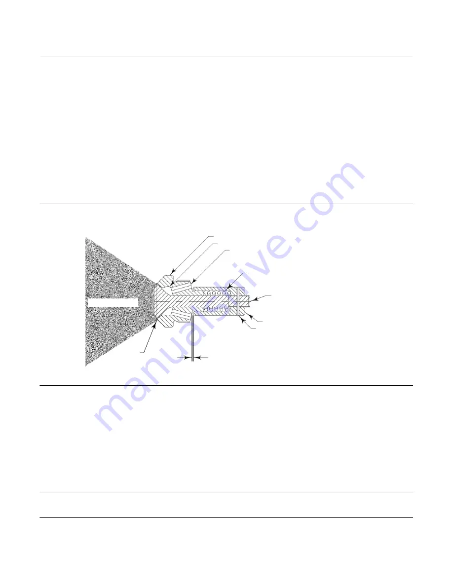
Figure 3. Fisher AF Nozzle Cross Section
A7191-2D
SPRAY HEAD
SWIRL CHAMBER
WATER INJECTION HOLES
(COMPOUND ANGLED ORIFICES)
SPRING
PLUG STEM
SPRING CASING
PIN
TRAVEL MEASUREMENT
SPRAY
ANNULUS
SPRAY PATTERN
Nozzle Maintenance and Replacement
When subjected to normal operating conditions, it is possible that wear, blockage, and/or weld fatigue will occur to
the valve body or nozzle assembly. During regularly scheduled maintenance, visually inspect the nozzles for wear and
blockage. Your local Emerson Service Center can help to determine the extent of weld fatigue and the correct course
of action. Poor performing nozzles or nozzle failure is typically caused by wear, corrosion, erosion, and/or blockage.
The following instruction will help to determine if any of these problems are present and provide a recommended
course of action for each.
Note
For optimal performance, nozzles should be inspected every 18-24 months and replaced every 24-36 months.


