
Instruction Manual
D103542X012
SS-263 Volume Booster
September 2019
7
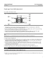
Diaphragm Assembly Replacement
CAUTION
Key numbers refer to figures 4 and 6.
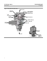
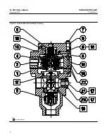
Figure 4. Diaphragm Assembly Drawing
GE47590-A
1. Remove the six cap screws (key 10) from the perimeter of the spring case assembly (key 3), and lift off the
assembly, taking care you do not lose the upper spring (key 6).
2. Remove the diaphragm assembly (key 4) and diaphragm spacer assembly (key 2) as a unit. The two small O-rings
(key 22) will stay attached to the diaphragm spacer assembly (key 2).
3. Separate the diaphragm assembly (key 4) from the diaphragm spacer assembly (key 2). Inspect the upper
diaphragm (key 4C) and the lower diaphragm (key 4B) for damage and replace if necessary.
Note
The diaphragms are not individually replaceable, but must be ordered as a diaphragm assembly (key 4).
4. Replace the two O-rings (key 22).
5. Carefully install the diaphragm assembly (key 4) into the diaphragm spacer assembly (key 2) by folding the upper
diaphragm (key 4C) inward. Rotate the diaphragm assembly (key 4) until the oversized hole in each diaphragm
aligns with the flow passage in the diaphragm spacer assembly (key 2).
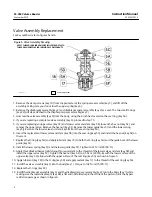
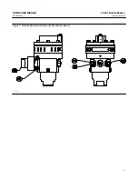
6. Install the diaphragm assembly (key 4) and the diaphragm spacer assembly (key 2) onto the body (key 1) while
making sure the lower diaphragm (key 4B) is flat and not folded or pinched. Orient the parts to form the bypass
restriction passage as shown in figure 6.
7. Apply lubricant (key 18) to the O-ring (4H) and the outside diameter of the spring seat (4F).
8. Install the upper spring (key 6) and the spring case assembly (key 3) on the upper diaphragm (key 4C).
CAUTION
To avoid damage to the diaphragms, do not overtighten the screws.
9. Replace the six cap screws (key 10) and tighten them in a crisscross manner using multiple patterns working up to a
final torque of 15.8 N•m (140 lbf•in).


