
Instruction Manual
D103542X012
SS-263 Volume Booster
September 2019
8
Valve Assembly Replacement
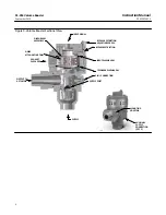
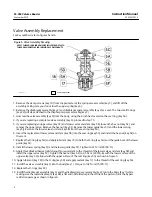
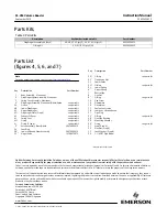
For key numbers refer to figures 5 and 6.
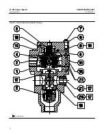
Figure 5. Valve Assembly Drawing
APPLY LUB/SEALANT
APPLY THREAD LOCKING ADHESIVE (MILD STRENGTH) TO
THREAD WHEN REPLACING INDIVIDUAL COMPONENTS
GE476000-A
1. Remove the six cap screws (key 10) from the perimeter of the spring case assembly (key 3), and lift off the
assembly, taking care you do not lose the upper spring (key 6).
2. Remove the diaphragm assembly (key 4) and diaphragm spacer assembly (key 2) as a unit. The two small O-rings
(key 22) will stay attached to the diaphragm spacer assembly (key 2).
3. Unscrew the valve assembly (key 5) from the body, using the 2-inch hex located on the seat ring (key 5A).
4. If you are replacing a complete valve assembly (key 5), proceed to step 10.
5. If you are replacing an upper valve (key 5C) and a lower valve and stem (key 5B), loosen the hex nut (key 5E), and
remove the upper valve. Remove the hex nut (key 5E). Remove the lower guide (key 5F) and the lower spring
(key 5J). Remove the lower valve and stem (key 5B) from the seat ring (key 5A).
6. Insert the replacement lower valve and stem (key 5B) into the seat ring (key 5A) and install the hex nut (key 5E) on
the stem.
7. Replace the O-ring (key 5H) and apply lubricant (key 18) to both the O-ring (key 5H) and the guide bore of the lower
guide (key 5F).
8. Install the lower spring (key 5J) and the lower guide (key 5F). Tighten to 61 N•m (45 lbf•ft).
9. Apply threadlock adhesive (mild strength) or equivalent to the threads of the lower valve and stem (key 5B) and
install the upper valve (key 5C). Tighten the hex nut (key 5E) to 4.5 N•m (40 lbf•in) with the lower surface of the
upper valve (key 5C) aligned with the upper surface of the seat ring (key 5A) as shown in figure 5.
10. Apply lubricant (key 18) to the O-ring (key 5D) and apply sealant (key 17) to the thread of the seat ring (key 5A).
11. Install the valve assembly (key 5) into the body (key 1). Torque to 102 N•m (75 lbf•ft).
12. Replace the O-rings (key 22).
13. Install the diaphragm assembly (key 4) and the diaphragm spacer assembly (key 2) onto the body (key 1) while
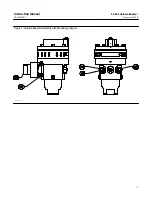
making sure the lower diaphragm (key 4B) is flat and not folded or pinched. Orient the parts to form the bypass
restriction passage as shown in figure 6.


