Type Y693
2
1. Flanged end connections and end connections for other than U.S. standard can usually be provided; consult the Fisher sales office or sales representative.
2. The pressure/temperature limits in this manual, and any applicable standard limitation, should not be exceeded.
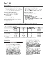
Specifications
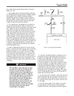
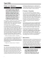
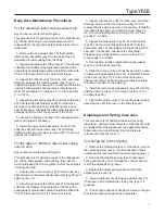
Installation
Personal injury, equipment damage, or
leakage due to escaping accumulated gas
or bursting of pressure-containing parts
may result if the gas blanketing regulator
is overpressured or is installed where
service conditions could exceed the
limits given in table 1, or where condi-
tions exceed any ratings of the adjacent
piping or piping connections.To avoid
such injury or damage, provide pressure-
relieving or pressure-limiting devices (as
required byTitle 49, Part 192, of the U.S.
Body Sizes and End Connection Styles
(1)
1-1/2 and 2 inch NPT screwed, Flanged ANSI
class 150 & 300 (Optional), or DIN class PN 16,
25, and 40 raised faced flanged (Optional)
Maximum Allowable Inlet Pressure
(2)
150 Psig (10.4 bar) or body rating limit
Maximum Outlet Pressure (Casing)
(2)
15 Psig (1.0 bar)
Outlet Pressure Ranges (2)
See table 1
Maximum Operating Outlet Pressure to Avoid
Internal Part Damage
(2)
2 Psig (0.14 bar) above outlet pressure setting
Material Temperature Capabilities
(2)
Nitrile:
- 20° to 180°F (- 29° to 82°C)
Fluoroelastomer:
+ 40° to 300°F (+ 5° to 149°C)
Elastomeric PTFE:
0° to 300°F (- 18° to 149°C)
Spring Case Connection
Aluminum Version:
3/4 inch NPT
Steel & Stainless Steel Version:
1/2 inch NPT
Approximate Weights
Aluminum Version:
22 lbs (9.9 kg)
Steel Version:
57 lbs (25.8 kg)
Steel & Stainless Steel with Aluminum Spring
Case:
35 lbs (15.8 kg)
Code of Federal Regulations, by the
National Fuel Gas Code Title 54 of the
National Fire Codes of the National Fire
Protection Association, or by other
applicable codes) to prevent service
conditions from exceeding those limits. A
regulator should be inspected immedi-
ately for damage after any overpressure
condition.
Additionally,physical damage to the gas
blanketing regulator could result in
personal injury and property damage due
to escaping accumulated gas. To avoid
such injury and damage, install the gas
blanketing regulator in a safe and well
ventilated location.
E
R
U
S
S
E
R
P
T
E
L
T
U
O
S
E
G
N
A
R
)
1
(
R
O
L
O
C
E
D
O
C
G
N
I
R
P
S
L
O
R
T
N
O
C
S
E
H
C
N
I
,
R
E
T
E
M
A
I
D
E
R
I
W
T
R
A
P
R
E
B
M
U
N
e
t
a
l
p
m
g
a
r
h
p
a
i
d
t
h
g
i
L
c
w
s
e
h
c
n
i
0
.
2
o
t
5
.
0
c
w
s
e
h
c
n
i
5
o
t
2
c
w
s
e
h
c
n
i
8
o
t
5
c
w
s
e
h
c
n
i
8
1
o
t
8
c
w
s
e
h
c
n
i
2
3
o
t
8
1
n
w
o
r
B
d
e
R
k
c
a
l
B
y
a
r
G
n
e
e
r
g
k
r
a
D
9
0
1
.
0
2
1
.
0
3
1
.
6
5
1
.
2
8
1
.
2
2
0
7
2
5
2
9
8
D
1
2
2
0
7
2
6
2
9
8
D
1
2
1
0
7
2
7
2
9
8
D
1
2
3
0
7
2
2
3
9
8
D
1
2
3
0
7
3
3
9
8
1
D
1
e
t
a
l
p
m
g
a
r
h
p
a
i
d
y
v
a
e
H
g
i
s
p
2
o
t
1
g
i
s
p
3
.
3
o
t
5
.
1
g
i
s
p
5
o
t
2
e
u
l
b
k
r
a
D
e
g
n
a
r
O
w
o
ll
e
Y
5
2
2
.
0
5
2
.
3
8
2
.
2
3
0
7
2
8
5
7
9
H
1
2
3
0
7
2
9
5
7
9
H
1
2
4
1
7
2
4
5
1
6
P
1
h
ti
w
e
t
a
l
p
m
g
a
r
h
p
a
i
d
y
v
a
e
H
y
v
a
e
h
d
n
a
p
a
c
g
n
i
s
o
l
c
s
s
a
r
b
r
o
t
s
u
j
d
a
g
n
i
r
p
s
y
t
u
d
g
i
s
p
5
.
5
o
t
2
g
i
s
p
0
1
o
t
4
e
p
i
r
t
s
n
e
e
r
G
r
e
v
li
S
3
6
3
.
6
0
4
.
2
2
0
7
2
4
6
6
0
Y
0
2
A
0
0
0
4
2
0
8
H
1
.
g
n
it
t
e
s
e
r
u
s
s
e
r
p
e
h
t
t
s
u
j
d
a
/
k
c
e
h
c
s
y
a
w
l
a
n
o
it
a
ll
a
t
s
n
i
r
e
tf
A
.
n
o
it
c
e
ri
d
y
n
a
n
i
d
e
n
o
it
i
s
o
p
l
e
r
r
a
b
g
n
i
r
p
s
e
h
t
h
ti
w
s
n
o
it
a
ll
a
t
s
n
i
r
o
f
e
r
a
s
e
g
n
a
r
e
r
u
s
s
e
r
p
t
e
lt
u
O
.
1
Table 1.
Outlet (Control) Pressure Ranges


