Instruction Manual
D103425X012
546NS Transducer
June 2021
5
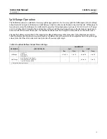
Table 1. Specifications (continued)
Adjustments
Zero and Span Adjustments:
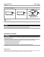
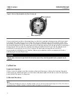
Screwdriver adjustments
located inside case (see figure 4)
Connections
Supply Pressure:
1/4 NPT internal located on side of
case, (or located on the 67CFR filter‐regulator if
mounted)
Output Pressure:
1/4 NPT internal located on side of
case
Vent:
1/4 NPT internal with screen located on relay
Electrical:
1/2 NPT internal located on bottom of case
Approximate Weight
4.1 kg (9 pounds)
Declaration of SEP
Fisher Controls International LLC declares this
product to be in compliance with Article 4 paragraph
3 of the Pressure Equipment Directive (PED)
2014/68/EU. It was designed and manufactured in
accordance with Sound Engineering Practice (SEP)
and cannot bear the CE marking related to PED
compliance.
However, the product
may
bear the CE marking to
indicate compliance with
other
applicable European
Community Directives.
NOTE: Specialized instrument terms are defined in ANSI/ISA Standard 51.1 -
Process Instrument Terminology.
1. The pressure/temperature limits in this document and any applicable standard or code limitation should not be exceeded.
2. Normal m
3
/hr—Normal cubic meters per hour (0
_
C and 1.01325 bar absolute). Scfh—Standard cubic feet per hour (60
_
F and 14.7 psia).
3. Performance values are obtained using a 546 transducer with a 4 to 20 mA DC input signal and a 0.2 to 1 bar (3 to 15 psig) or a 0.4 to 2 bar (6 to 30 psig) output signal. Ambient temperature
is 24
_
C (73
_
F). A transducer with other input or output signals might exceed these values. Reference accuracies of
±
3.5% can be expected with output ranges starting near zero psig.
4. Reference accuracy includes the effects of non-linearity, hysteresis, and deadband per SAMA Standard PMC 20.1-1973.
Table 2. Electromagnetic Immunity Performance
Port
Phenomenon
Basic Standard
Test Level
Performance Criteria
(1)
Enclosure
Electrostatic discharge (ESD)
IEC 61000‐4‐2
4 kV contact
8 kV air
A
Radiated EM field
IEC 61000‐4‐3
80 to 1000 MHz @ 10V/m with 1
kHz AM at 80%
A
Rated power frequency magnetic field
IEC 61000‐4‐8
60 A/m at 50 Hz
A
I/O signal/control
Burst (fast transients)
IEC 61000‐4‐4
1 kV
A
Surge
IEC 61000‐4‐5
1 kV (line to ground only, each)
A
Conducted RF
IEC 61000‐4‐6
150 kHz to 80 MHz at 3 Vrms with
1kHz AM at 80%
A
Specification limit =
±
1% of span
1. A=No degradation during testing. B = Temporary degradation during testing, but is self‐recovering.
For Declaration of Conformity available in multiple languages:
Installation
WARNING
Warning - Explosion Hazard
Do not connect or disconnect this equipment unless power has been removed or the area is known to be nonhazardous.
AVERTISSEMENT
Avertissement- Risque d'explosion
Ne pas debrancher tant que le circuit est sous tension, a moins qu'il ne s'agisse d'un emplacement non dangereux.

