


Instruction Manual
D200149X012
3610J and 3620J Positioners
September 2017
25
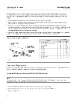
4. Apply an input signal (pneumatic or electrical) to the positioner to position the actuator at approximately
mid‐travel. If necessary, you can use the zero adjustment to position the actuator at approximately mid‐travel. The
actuator should not be under load during crossover adjustment.
Note
Large step changes may cause the supply pressure gauge reading to momentarily drop.
pressure gauge reads zero pressure; then turn it clockwise until full supply pressure is obtained. Once supply
pressure is obtained, turn the adjusting screw an additional four, 360‐degree turns clockwise. The gauge should
read supply pressure.
6. Continue calibration by performing the zero and span adjustments.
Piston Actuators (3610JP, 3611JP, 3620JP, or 3621JP Positioners)
Note
Do not perform these steps 1 through 6 if calibrating a 3610J or 3620J positioner. These 6 steps are only applicable to 3610JP,
3611JP, 3620JP, and 3621JP positioners used on piston actuators.
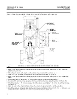
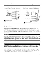
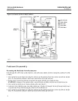
1. Unscrew the four captive cover screws and remove the cover (key 41, figure 28).
2. If the positioner does not have pressure gauges, connect pressure gauges to OUTPUT A and OUTPUT B.
3. Apply supply pressure.
4. Apply an input signal (pneumatic or electrical) to the positioner to position the actuator at approximately
mid‐travel. If necessary, you can use the zero adjustment to position the actuator at approximately mid‐travel. The
actuator should not be under load during crossover adjustment.
Note
Large step changes may cause the supply pressure gauge reading to momentarily drop.
5. Using a screwdriver, turn the crossover adjusting screw (key 13) until the sum of the OUTPUT A and OUTPUT B
pressures is 140 to 160 percent of supply pressure. Clockwise rotation increases the OUTPUT A and OUTPUT B
pressures.
Note
Make sure that neither the OUTPUT A pressure or the OUTPUT B pressure equal the supply pressure when adjusting the crossover
screw. If either pressure is equal to supply, an accurate crossover setting cannot be achieved. This may occur with the 3611JP or
3621JP positioner due to the spring(s) in the 585, 585R, 585C, or 585CR actuator. If one of the cylinder pressures equals supply
pressure when adjusting the crossover, do one or both of the following: