2. Change the control spring (key 6) to match the
desired spring range.
3. Replace the adjusting screw (key 35).
4. Install the replacement closing cap gasket (key 25)
if necessary and reinstall the closing cap (key 22).
5. If the spring was changed, be sure to change the
stamped spring range on the nameplate.
To Disassemble and Reassemble the Diaphragm Parts
1. Remove the closing cap (key 22) and turn
adjusting screw (key 35) counterclockwise to
remove adjusting screw, baffle plate (key 56) and
control spring (key 6).
2. Remove the spring case hex nuts (key 23,
not shown), cap screws (key 24) and spring
case (key 3).
3. Remove the diaphragm (key 10) and attached
parts by tilting them so that the pusher post (key 8)
slips off the lever assembly (key 16). To separate
the diaphragm (key 10) from the attached parts,
unscrew the machine screw (key 38) from the
pusher post (key 8).
4. Inspect the pusher post (key 8) and the body seal
O-ring (key 11), replace if required.
5. Remove hex nut (key 21) to separate the
diaphragm (key 10) and attached parts.
6. To replace the lever assembly (key 16), remove
the machine screws (key 17). To replace the stem
(key 14) or access the stem seal O-ring (key 30)
also perform Body Area Maintenance procedure
steps 1 and 4 and pull the stem out of the
diaphragm casing (key 4).
7. Install the stem (key 14) into the guide insert
(key 18)and perform Body Area Maintenance
procedure steps 6 through 8 as necessary.
8. Install the lever assembly (key 16) into the stem
(key 14) and secure the lever assembly with the
machine screws (key 17).
9. Install the parts on the pusher post in the order
listed below:
• Pusher Post (key 8)
• Pusher Post Connector (key 40)
• Connector Seal O-ring (key 49)
• Diaphragm Head (key 7)
• Diaphragm (key 10), pattern side up
• Diaphragm Head (key 7)
• Hex Nut (key 21) — Tighten the hex nut 9 to
11 ft-lbs / 12 to 15 N•m to secure parts to the
pusher post connector (key 40)
• Overpressure Spring (key 39)
• Spring Holder (key 37)
• Machine Screw (key 38)
10. Insert and tighten the machine screw (key 38) with
a torque of 1 to 3 ft-lbs / 1.3 to 4.1 N•m to secure
the diaphragm parts to the pusher post (key 8).
11. Install the assembled parts in the diaphragm
casing (key 4). Make sure the lever (key 16) fits
in the pusher post (key 8) and that the holes in
the diaphragm (key 10) align with the holes in the
diaphragm casing.
12. Place the spring case (key 3) on the diaphragm
casing (key 4) so the vent assembly (key 26) is
oriented correctly and secure with the cap screws
(key 24) and hex nuts (key 23, not shown) finger
tight only.
13. Insert the control spring (key 6) into the spring
case (key 3), followed by the baffle plate (key 56)
and adjusting screw (key 35).
14. Turn the adjusting screw (key 35) clockwise until
there is enough spring (key 6) force to provide
proper slack to the diaphragm (key 10). Using a
crisscross pattern, tighten the cap screws (key 24)
and hex nuts (key 23, not shown) to 14 to
17 ft-lbs / 19 to 23 N•m of torque. To adjust the
outlet pressure to the desired setting, refer to
Startup and Adjustment section.
15. Install a replacement closing cap gasket (key 25)
if necessary and then install the closing cap
(key 22).
Parts Ordering
When corresponding with your local Sales Office about
this equipment, reference the equipment serial number
or FS number found on a nameplate attached to the
bonnet. When ordering replacement parts, reference
the eleven digit part number of each needed part found
in the parts list.
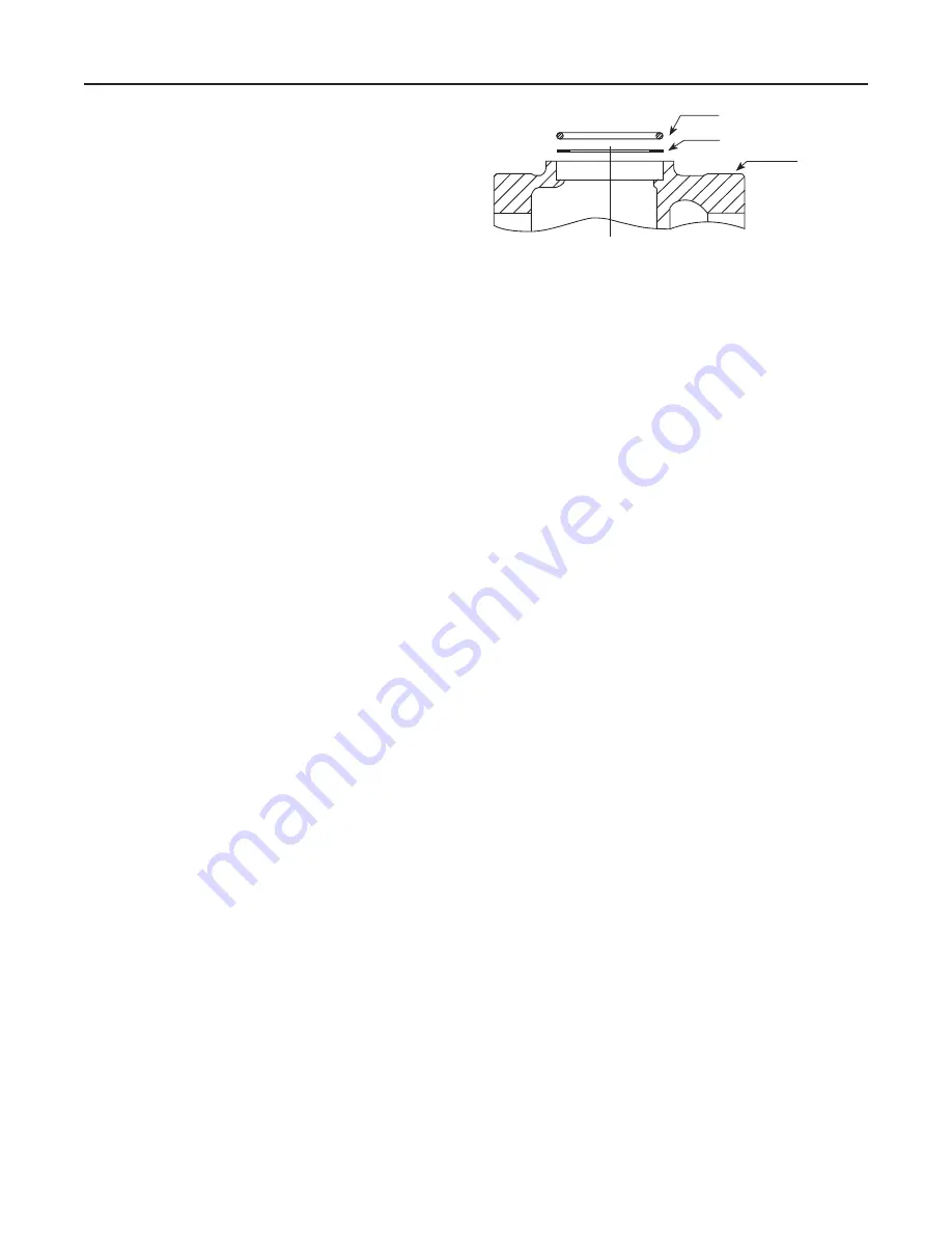
Figure 3.
Expanded View of the Body Area
Showing the O-ring and Backup Ring Placement
BODY SEAL O-RING (KEY 11)
BACKUP RING (KEY 50)
BODY (KEY 1)
7
161 Series


