


Instruction Manual
D101322X012
1051 and 1052 Size 33 Actuators
June 2017
6
For push‐down‐to‐open action
, the valve ball or disc should be in the fully closed position (see the valve body
instruction manual).
5. Make sure that the index markings on the valve shaft are properly aligned with the markings on the lever and slide
the valve shaft into the lever. Install the valve mounting cap screws, washers, and nuts and tighten to the torque
value given in the appropriate valve body instruction manual.
6. Ensure all end play in the valve shaft is removed by pulling the valve shaft toward the actuator as much as possible.
Make sure the actuator rod is perpendicular to the valve shaft. Refer to the valve instruction manual for specific end
play considerations.
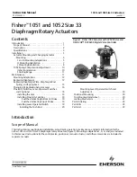
Figure 3.Travel Stops and Switch Positions on the Fisher 1051 and 1052 Size 33 Actuator
HOUSING COVER
ASSEMBLY (KEY 33)
PROXIMITY
SWITCHES
MOUNTING POSITION FOR
SWITCH INDICATING
TOP OF STROKE
(ACTIVATED BY
OUTER CAM)
YOKE
MOUNTING
BOSS
UP TRAVEL
STOP
DOWN TRAVEL STOP
MOUNTING POSITION FOR SWITCH
INDICATING BOTTOM OF STROKE
(ACTIVATED BY INNER CAM)
W4738
CAUTION
When adjusting the travel stop for the closed position of the valve ball or disc, refer to the appropriate valve instruction
manual for detailed procedures. Undertravel or overtravel at the closed position may result in poor valve performance
and/or damage to the equipment.
WARNING
To avoid personal injury and equipment damage from moving parts, keep fingers and tools clear while stroking the
actuator with the cover removed.
9. Stroke the actuator and adjust the down travel stop so that the valve ball or disc is in the desired position.