


Transducer Block
November 2010
69
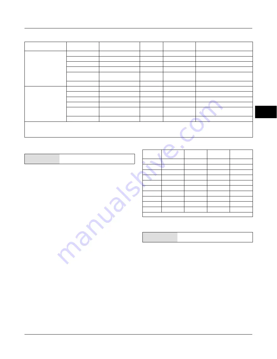
Table 4-11 . Output Block PV Status
FEATURE_SEL
PW Alarms Set PV Status
Transducer Mode,
Actual
Active PlantWeb
Alarms
AO / DO
PV Status
(2)
AO / DO
PV Substatus
AO/DO PV
Limit Substatus
(1)
Enabled
OOS
X
Bad
Device Failure
Constant
Man
X
Bad
Non-specific
Constant
Auto
Fail
Uncertain
Subnormal
Auto
Maintenance, no Fail
Uncertain
Non-specific
Auto
Advisory, no Fail, no
Maintenance
Good
Advisory
Auto
None
Good
Non-Specific
Not Enabled
OOS
X
Bad
Device Failure
Constant
Man
X
Bad
Non-Specific
Constant
Auto
Fail
Good
Non-Specific
Auto
Maintenance, no Fail
Good
Non-Specific
Auto
Advisory, no Fail, no
Maintenance
Good
Non-Specific
Auto
None
Good
Non-Specific
NOTES:
X
=
No Effect
1. PV limit substatus reflects only READBACK limit substatus. SP limit substatus reflects only out block rate limits.
2. Firmware Revision 1.1 and earlier will set AO/DO PV Status to Bad if Feedback Sensor has failed, i.e.; Travel Sensor Fail. However, if the Travel Sensor fails, and the instrument
falls back to pressure, PV Status will remain good.
MAI Channel Map
Field Communicator
TB > Configure/Setup > Detailed Setup
>
MAI
Channel Map
Allows the user to specify which transducer block
parameter is available through each of the MAI Block
channels (MAI_CHANNEL_1 through
MAI_CHANNEL_8 [95.1 through 95.8]). Transducer
block parameters available to each channel:
1
1
= FINAL_VALUE
1
2
= TRAVEL_TARGET
1
3
= FINAL_POSITION_VALUE
1
4
= TRAVEL
1
5
= SUPPLY_PRESS
1
6
= ACT_PRESS_A
1
7
= ACT_PRESS_B
1
8
= ACT_PRESS_DIFF
1
9
= DRIVE_SIGNAL
10
= TRAVEL_DEVIATION
11
= TEMPERATURE
12
= CYCLE_COUNT
13
= TRAVEL_ACCUM
Table 4-12. Limit Sub Status
Out
Block
Transducer
Mode
In Cutoff
Region
Rate
Limited
Limit
Sub-Status
AO, DO
OOS
X
X
Constant
AO, DO
MAN
X
X
Constant
AO
AUTO
High
X
High Limited
AO
AUTO
Low
X
Low Limited
AO
AUTO
X
High
High Limited
AO
AUTO
X
Low
Low Limited
AO
AUTO
None
None
Not Limited
DO
AUTO
X
High
High Limited
DO
AUTO
X
Low
Low Limited
DO
AUTO
X
None
Not Limited
NOTE: X
=
No Effect
Alert Handling
Field Communicator
TB
>
Configure/Setup
>
Detailed Setup
>
Alert
Handling
PlantWeb Alert Simulate
When enabled, PlantWeb Alert Simulate
(PWA_SIMULATE [39])
allows the user to write to the
following PlantWeb and Instrument alert parameters;
Failed Active, Maintenance Active, Advise Active,
Environment Active, Travel Active, Proximity Active,
Travel History Active, Performance Active, PD Event
Active, PD Detail 1 Active, PD Detail 2 Active, PD
Detail 3 Active, PD Detail 4 Active, PD Detail 5 Active,
PD Detail 6 Active. This provides a way to simulate
4
Summary of Contents for FIELDVUE DVC6200f
Page 42: ...DVC6200f Digital Valve Controller November 2010 30 4 ...
Page 60: ...DVC6200f Digital Valve Controller November 2010 48 4 ...
Page 108: ...DVC6200f Digital Valve Controller November 2010 96 4 ...
Page 122: ...DVC6200f Digital Valve Controller November 2010 110 4 ...
Page 188: ...DVC6200f Digital Valve Controller November 2010 176 4 ...
Page 200: ...DVC6200f Digital Valve Controller November 2010 188 4 ...
Page 216: ...DVC6200f Digital Valve Controller November 2010 204 5 ...
Page 250: ...DVC6200f Digital Valve Controller November 2010 238 8 ...
Page 254: ...DVC6200f Digital Valve Controller November 2010 242 A ...
Page 284: ...DVC6200f Digital Valve Controller November 2010 272 D ...
Page 290: ...DVC6200f Digital Valve Controller November 2010 278 E ...
Page 308: ...DVC6200f Digital Valve Controller November 2010 296 F ...
Page 312: ...DVC6200f Digital Valve Controller September 2010 300 Notes G Glossary ...
Page 324: ...DVC6200f Digital Valve Controller November 2010 312 F Index ...


