


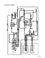

1-6-2
T5553EA
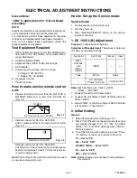
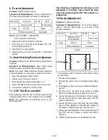
3-1. H Adjustment
Purpose:
To get correct horizontal position and size of
screen image.
Symptom of Misadjustment:
Horizontal position and
size of screen image may not be properly displayed.
Note:
R583 --- Main CBA
1. Connect Frequency Counter to R583.
2. Set the unit to the VIDEO mode and no input is
necessary. Enter the Service mode.
(See page 1-4-1.)
3. Operate the unit for at least 20 minutes.
4. Press "2" button on the remote control unit and
select H-Adj mode. (Press "2" button, then display
will change H-Adj and AGC.)
5. Press "CH
o
/
p
" buttons on the remote control
unit so that the display will change "0" to "7."
At this moment, choose display "0" to "7" when the
Frequency counter display is closest to
15.734kHz
±
300Hz.
6. Turn the power off and on again.
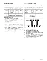
3-2. C-Trap Adjustment
Purpose:
To get minimum leakage of the color signal
carrier.
Symptom of Misadjustment:
If C-Trap Adjustment is
incorrect, stripes will appear on the screen.
Note:
J271 (B-Out)--- Main CBA
1. Connect Oscilloscope to J271.
2. Input a color bar signal from RF input.
Enter the Service mode. (See page 1-4-1.)
3. Press "0" button on the remote control unit and
select C-TRAP mode.
4. Press "CH
o
/
p
" buttons on the remote control
unit so that the carrier leakage B-Out (3.58MHz)
value becomes minimum on the oscilloscope.
5. Turn the power off and on again.
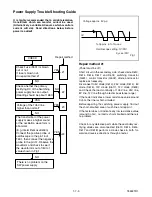
Test point
Adj. Point
Mode
Input
R583
CH
o
/
p
buttons
Video
---
Tape
M. EQ.
Spec.
---
Frequency Counter
15.734kHz
±
300Hz
Test point
Adj. Point
Mode
Input
J271
(B-OUT)
CH
o
/
p
buttons
---
Color Bar
Tape
M. EQ.
Spec.
---
Oscilloscope
Pattern Generator
---
Figure
minimum
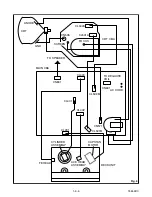
Fig. 2
Summary of Contents for EWC1303A
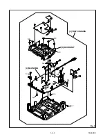
Page 16: ...1 5 2 T5553DC S 1 1 REAR CABINET S 1 S 2 Fig 1 Fig 2 1 REAR CABINET S 1 S 2 S 1 S 1 S 1 ...
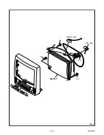
Page 18: ...1 5 4 T5553DC Fig 4 S 8 S 8 S 8 S 8 ANODE CAP 5 CRT CRT CBA ...
Page 55: ...1 14 3 T5553PEX Packing X3 X4 X2 TAPE X1 X7 X5 S2 S6 S3 S1 S4 FRONT S15 ...
Page 67: ...EWC1303A T5553UD 2004 01 20 ...